
Cinema 4D tutorial: Basics & 3D practice for beginners

- Find your way around the Cinema 4D environment, know the control panels, functions and objects.
- Learn how to use the tools for modeling, lighting and rendering 3D objects.
- Make practical use of Cinema 4D right from the start by working on concrete examples.
- 200 PDF pages on new functions in Cinema 4D R19, including working materials
- Update: Over 100 PDF pages on the new functions in Cinema 4D R20, including working materials
Extruding, rendering and beveling - is all of this still completely or largely foreign to you? After this training course, you will know the C4D terms and functions and be able to create your own 3D objects.
54 Videos, 432 minutes
Introduction to the UI, using and editing parametric basic objects
Cinema 4D for beginners - 3D practice: 1.1 Intro
Presentation of the training: In the first part, you will learn the basic concepts of modeling, textures, lighting and rendering. In the second part, we then focus on a creative project, more precisely: we build a stage spotlight - from A to Z, from start to finish. Conclusion: This training is primarily aimed at creative modeling and setting the scene, rather than animation.
Cinema 4D for beginners - 3D practice: 1.2 version
Cinema 4D is available in four different versions. In this clip I will introduce you to the four versions and we will also make the first important presettings so that you can work comfortably right from the start. Finally, I will introduce you to the three most important "managers". This is what the control panels or "palettes" are called in Cinema 4D.
Cinema 4D for beginners - 3D practice: 1.3 units
The display of the unrendered scenes can be adapted to the respective tasks in Cinema 4D. Here you can find out which display option is best suited for modeling and where you can set this option. You also have the option of either retaining the default unit of measurement "cm" or changing it if required.
Cinema 4D for beginners - 3D practice: 1.4 Basic objects
Using a cube and a cylinder, you will learn what the so-called "basic parametric objects" are and how you can customize them. These objects come in very different forms. You either need them for what they are, i.e. cubes, beams, plates, rods, cylinders or landscapes, or you can use them as the basis for more complex objects that can be edited on a polygon basis.
Cinema 4D for beginners - 3D practice: 1.5 Navigating
A scene should always be viewed from different perspectives in order to be able to visualize the spatial arrangement of the objects. Here you can find out how to move around in a C4D scene and which keyboard shortcuts to use, and what to do if an object gets "lost" in the infinite space of Cinema 4D.
Cinema 4D for beginners - 3D practice: 1.6 Isometry
Technical modeling in particular often requires a so-called isometric view of the scene. This involves using a camera that is not subject to perspective and displays everything exactly from above, below, left, right, front or behind. Apart from that, I'll tell you a few more things about the way unrendered scenes are displayed in Cinema 4D.
Cinema 4D for beginners - 3D practice: 1.7 Moving/Rotating/Scaling
Objects can be moved, rotated or scaled. In this clip you will get to know the corresponding tools, but you will not only learn how to use them, but also what you should never do with them: The dos and don'ts are easy to grasp and, especially at the beginning, contribute greatly to a problem-free handling of the scene.
Cinema 4D for beginners - 3D practice: 1.8 Workshop basic objects
In this clip, you can show what you have learned: We build a cooking pot from basic parametric objects. To do this, you will need the commands and tools that you learned in the first chapter of this training course. In addition to two cylinders and a ring, it is also about the clever selection of suitable basic objects, the creation of curves and the clever use of object coordinates.
Working with polygon objects
Cinema 4D for beginners - 3D practice: 2.1 mode
If you convert a parametric basic object into a polygon object, all points, edges and surfaces of the object can be edited. Similar to Photoshop, selections are used to deform parts of an object or to select certain edges or points that can then be moved, rotated or scaled. There are several ways to create a selection - the simplest one is explained here: the live selection tool.
Cinema 4D for beginners - 3D practice: 2.2 Selecting and optimizing
Selecting individual polygons can be quite tedious, especially with fine-resolution objects. For this reason, there are other selection methods that work better for large polygon sets. If the polygons are to be deleted after selection, a so-called optimization should be carried out after deletion: The points that are still present despite the deletion of the polygons are permanently removed from the object.
Cinema 4D for beginners - 3D practice: 2.3 Extruding
The two commands "Extrude" and "Extrude inside" are among the most important modeling commands. Together with the live selection, these two commands can be used to create almost any shape. In this clip, you will find out what the difference is to moving individual polygon groups and how much creative variety can be created with these two commands alone.
Cinema 4D for beginners - 3D practice: 2.4 Polygon pen
The polygon pen is a really great and versatile construction tool. You can use it to generate different shapes without any input from other objects, link them together and thus create very detailed models. The polygon pen can create both edges and polygons and automatically understands whether the cursor is approaching a point or an edge in order to move it or connect it to another edge.
Cinema 4D for beginners - 3D practice: 2.5 SDS
The SDS is an object to which both parametric basic objects and polygon objects can be subordinated. The edges of the subordinate objects are rounded by the SDS according to their structure. You can think of it like rounding a path in 3D space by converting its corner points into curve points.
Cinema 4D for beginners - 3D practice: 2.6 Knife tools
The knife tools are used to divide polygon objects more finely. This subdivision, i.e. the cutting of the polygon structure, can be defined very finely and precisely. This tool is also used in SDS modeling: If a cut is made close to an edge of an object, it can be used to reduce a rounding that is too soft.
Cinema 4D for beginners - 3D practice: 2.7 Box Workshop Part 1
Small intermediate workshop part 1: A loudspeaker box is to be built from a cube. To do this, we place the cube structure in such a way that an even opening can be created in the lower part of the box. A disk is then placed in this opening, after which the two objects are joined together so that the remaining gap around the disk can be closed.
Cinema 4D for beginners - 3D practice: 2.8 Box workshop part 2
After closing the opening around the disk, we place the speaker in an SDS and start to shape the cone into a bass speaker using a combination of "extruding" and "extruding inside". The dome is made from a sphere, and the knife tool is used at the end to create slightly less rounded edges.
Volume generators and deformers
Cinema 4D for beginners - 3D practice: 3.1 Spline Lathe
Splines are nothing more than paths that may already be familiar from other programs. Together with a "Lathe", you can use them to create rotational solids. In this clip, we use this method to create a glass with just a few clicks. The great thing about it is that the spline remains active even after the object has been created and can be changed at any time.
Cinema 4D for beginners - 3D practice: 3.2 Spline Sweep
All types of irregular splines can be created very easily using the spline pen. The various modes of the tool allow quite intuitive editing or correction of the anchor points. If a second spline is created, both can be added together to form a volume using a "sweep". In this case too, both splines are retained and can be modified or replaced at any time.
Cinema 4D for beginners - 3D practice: 3.3 Extrude text spline
As the name suggests, the Extrude object extrudes closed splines and thus creates a volume. In this clip, we are using the text spline tool, as it makes it easy to create words or even entire texts and convert them into 3D text. The edges of the letters can be rounded off in a variety of ways or given their own contour.
Cinema 4D for beginners - 3D practice: 3.4 Modeling objects
Modeling objects are a great help when modeling very specific objects. In this movie, we look at the array, which can be used to distribute objects concentrically in the scene, the symmetry object, which can mirror an object subordinate to it along one of the three spatial axes, and the atom array, which creates a kind of skeleton or framework from each body that is subordinate to it.
Cinema 4D for beginners - 3D practice: 3.5 Bevel
The edges of parametric basic objects can be rounded very easily. This rounding, also known as "beveling", must be achieved differently for polygon objects. On the one hand, there is a command that allows not only rounding, but also more complex transitions between two polygons. On the other hand, if the main purpose is to round an edge, there is the so-called bevel deformer, which is simply subordinated to a polygon object.
Cinema 4D for beginners - 3D practice: 3.6 Deformer
Deformers are auxiliary objects that are simply subordinated to a polygon mesh and can therefore perform very different tasks. In this clip, I introduce you to the bend deformer and show you how to make it bend an object. You'll also get to know the twist deformer.
Cinema 4D for beginners - 3D practice: 3.7 Wind turbine
In this short intermediate workshop, you can once again show what you have learned. With the help of the array object and a few other components, we will build a wind turbine. Even if you could certainly build such a system in more detail, this mini-workshop will help you to build a scene that is at least easily recognizable using simple modelling techniques.
Light sources and materials
Cinema 4D for beginners - 3D practice: 4.1 Area light source
The area light source is one of several options for illuminating an object or scene. In order for it to function as expected from a light source, it must be assigned a shadow and a fall-off. In comparison, in this film you will also get to know the physical light source, which is already equipped with shadows and a fall-off and therefore behaves physically correctly.
Cinema 4D for beginners - 3D practice: 4.2 Target spot
Neither the area light source nor the physical light source can be assigned a so-called visibility. This refers to a type of atmosphere that is assigned to the light source and that simulates a cone of light in a smoky or foggy room. For this purpose, we create a target spot, which also has the great advantage of always being automatically directed at a zero object. This makes it easy to aim it at specific objects.
Cinema 4D for beginners - 3D practice: 4.3 Sky
For outdoor scenes, Cinema 4D provides two lighting objects: a physical sky that illuminates similarly to a real sky - on the one hand through the sky dome, and on the other, if desired, with a sun object. It can also be used to display various types of clouds, including rainbows, fog, stars and ozone. The other object for lighting outdoor scenes is the "sky object"; however, this requires an HDRI in order to emit realistic-looking light onto the scene.
Cinema 4D for beginners - 3D practice: 4.4 Material editor
All the channels, i.e. properties, that are important for a material can be created in the material editor. This first clip deals with the channels for color, reflectivity, transparency, relief and displacement. Reflectivity in particular, which has been completely redeveloped in the R16 version, provides a wide range of settings. As every material has some kind of reflectivity, this channel and its physically correct reproduction are key to realistic-looking materials.
Cinema 4D for beginners - 3D practice: 4.5 Physical
Physically correct materials not only dispense with the installation of a highlight, but also partially replace elaborate render effects such as ambient occlusion and global illumination. You can find out how to set the reflectivity correctly using a "physical material" in this clip.
Cinema 4D for beginners - 3D practice: 4.6 Material assignment
You can assign several materials to the same object. This is particularly important if, for example, you want to place a label or create several colors. In this video, I will show you how you can map different materials to an object using selections that you can "freeze", i.e. save.
Camera and rendering
Cinema 4D for beginners - 3D practice: 5.1 Camera object
In addition to the standard camera, which is normally sufficient for modeling a scene, you can create your own camera objects. These have the advantage that you can not only position them precisely and place them in the scene in a motion-safe manner, but also use the adjustable focal length. If you also use the physical renderer, you can also render motion blur and depth of field.
Cinema 4D for beginners - 3D practice: 5.2 Render settings
In Cinema 4D, the material settings are very closely related to the renderer used. We compare classic materials and classic render settings with new, physically correct materials and the physical renderer. You can see that materials that are based on physically measurable variables such as roughness, reflection strength and Fresnel settings look much more realistic than the "old" materials.
Cinema 4D for beginners - 3D practice: 5.3 Photoshop
Of course, most renderings are further processed in other programs such as Photoshop or After Effects. We render our render scene in the image manager, save it and then open the file in Photoshop. The special thing about this is that we create a separate render channel for each object in the scene, which makes it much easier to post-process the individual parts in Photoshop, as we can use existing alpha channels and save time-consuming cropping.
Modeling of the headlamp body
Cinema 4D for beginners - 3D practice: 6.1 Laying splines
To ensure that the spline looks exactly as specified by the headlight shape, we load an image of the headlight into the front view of Cinema 4D. Then we set the spline, but only corner points. The points that should actually be rounded are then selected and gently rounded using the chamfer command.
Cinema 4D for beginners - 3D practice: 6.2 Extruding
We create a single overall spline from the original spline and the mirrored spline. This is then subordinated to an extrude object and extruded to such an extent that it corresponds exactly to the thickness of the front and rear parts of the camera body. The edges of the top surfaces are rounded so that they do not look too sharp-edged and therefore unrealistic.
Cinema 4D for beginners - 3D practice: 6.3 Building a tube
The inner cover surface of the back part is first extruded on the inside, then extruded. We use the symmetry object to create the front part, which is identical to the rear part. We then extrude the actual headlight housing from the spline, which is still present. It is slightly too large, so it has to be fitted into the front and rear parts by scaling the spline.
Cinema 4D for beginners - 3D practice: 6.4 Cooling fins
The cooling plates that surround the entire housing are formed from a simple cube. The first cube is placed and fitted into place on one side, then duplicated. This is how we arrange all 5 cooling plates one after the other. The SSAO switched on helps to create a three-dimensional impression of the scene.
Cinema 4D for beginners - 3D practice: 6.5 lids
A rounded end plate is missing on the top of the headlight. We create it from the body, converting the somewhat irregular spline into an even one beforehand. This creates a second body. By selecting the desired polygons on the upper side and deleting the superfluous ones, only the curved sheet on the upper side remains. The sheet is extruded at the end to give it a typical sheet thickness of 1.5 mm.
Cinema 4D for beginners - 3D practice: 6.6 Boole
Although it is not absolutely necessary to drill a hole in the front of the headlight for modeling purposes, anyone who would like to place a light source in the housing later may be grateful if they know how to do this using a Boole object. We then build the ring that connects the bayonet to the headlight housing from a finely resolved cylinder.
Cinema 4D for beginners - 3D practice: 6.7 Bayonet
The cylinder, on which the three protrusions for the lens bayonet are mounted, is constructed from an axially symmetrical mirrored half cylinder. By selecting, extruding and then beveling with a bevel deformer, all edges are given a perfect technical rounding.
Cinema 4D for beginners - 3D practice: 6.8 Lens
The headlight's projection lens is made from a simple cylinder. We use an elegant technique to model the characteristic transition at the rear and the end for the foil holder at the front: we model both by selecting and extruding the edges.
Cinema 4D for beginners - 3D practice: 6.9 Rotation mechanics
Modeling the locking disc is not technically difficult. All you really need to do is get an idea of how this mechanism works and what it is made of. We therefore take a look at a detailed photo of the mechanism and model it using various basic objects.
Cinema 4D for beginners - 3D practice: 6.10 Bow shape
A spotlight normally has a bracket on which it can be hung in a crossbar. We design the bracket in the front view using a spline. The Structure Manager helps us to set the points at right angles. Then the two corner points are chamfered and the spline is subordinated to an extrude object.
Cinema 4D for beginners - 3D practice: 6.11 Bow curvature
To give the bow a realistic thickness and, above all, its typical outward curvature, we first select its outer edges using a loop selection. We create the curvature in five small extrusion steps, each of which differs by an angle of 15°, and then the entire bow is extruded.
Cinema 4D for beginners - 3D practice: 6.12 Screw
Technical objects such as this headlight "live" from details. We therefore need to attach the bracket to the housing on both sides with a screw. The screw is modeled from a basic oil tank object and a cube using the Boolean object. A cylinder provides the missing washer.
Cinema 4D for beginners - 3D practice: 6.13 Holes
The bracket has five round recesses, the technical sense of which is only partially clear to me, but these five holes are definitely part of the bracket's design. We take a cylinder and duplicate it four times using the duplicate command. The null object, which contains the five cylinders, is now placed with the bracket in a Boolean object, which is how the holes are created.
Cinema 4D for beginners - 3D practice: 6.14 Grip screw
Another very characteristic component of the headlight is a nicely rounded, smooth handle screw. We model it from a cylinder, the top of which is roughly pre-rounded by hand. The "fingers" of the handle are also pre-modeled. After optimizing the cylinder, an SDS object takes over the rounding of the originally very angular cylinder.
Cinema 4D for beginners - 3D practice: 6.15 Add-on
I would also like to show you how various technical details such as the bayonet lock were modeled. But if you've managed so far, you can easily model these details yourself. That's why I'd rather show you here how to transfer existing data into a scene. Tip: The same command is also available for the materials in the Material Manager.
Cinema 4D for beginners - 3D practice: 6.16 HDRI
To make the shiny sheet metal shine, we need a so-called HDRI: a high dynamic range image that is mapped onto the sky object. The HDRI then surrounds the entire scene so that the reflections look very realistic after rendering.
Cinema 4D for beginners - 3D practice: 6.17 Standard material
The standard material should be dark painted sheet metal. If you want a physically correct material, you need nothing more than the reflectivity channel. This allows both the color and gloss properties of the paint to be applied there.
Cinema 4D for beginners - 3D practice: 6.18 Glass, aluminum
For the areas where the worn, unpainted sheet metal will later be visible, we now create another material that should look like metal. We also need glass, which will be used for the front lens.
Cinema 4D for beginners - 3D practice: 6.19 Vertex Map
A vertex map is a type of matrix that is placed directly on the geometry, or more precisely on the points that make up the geometry (vertex points). If you only select certain points on this vertex map by "painting", these will later determine where the dark paint and the bare sheet metal should be visible.
Cinema 4D for beginners - 3D practice: 6.20 Vertex mapping
The vertex map must now mediate between the dark and the metallic material. A folder is created for this purpose, which is switched to "Layer mask" mode. The highlight, however, is a noise map calculated in "Levr" mode, which produces very realistic results.
Cinema 4D for beginners - 3D practice: 6.21 Light setting
A floor is needed to round off the scene, because without it, no shadows can be captured. However, for the floor to be as bright as the background, it needs a render tag with a very specific configuration. A target spot provides crisp contrasts and effective ambient lighting.
Cinema 4D for beginners - 3D practice: 6.22 Render settings
The scene is rendered with the physical renderer, which also allows blurred areas to be rendered. Before we take a look at the render presets and adjust them to our needs, you will learn how to create a new camera, switch it on and adjust it.
Update: New features in Cinema 4D R19

C4D Release 19 - the improved sound effector

C4D Release 19 - the extended Voronoi break object

C4D Release 19 - the physics-based GPU renderer ProRender

C4D Release 19 - Scene reconstruction with the motion tracker

C4D Release 19 - improved polygon reduction and variable level of detail (LOD)

C4D Release 19 - a selection of practical workflow improvements
Update: New features in Cinema 4D R20

C4D Release 20 - Volume-based modeling with OpenVDB

C4D Release 20 - Node-based materials

C4D Release 20 - Fields (Basic and Advanced Fields)

C4D Release 20 - further practical improvements and new functions
Examples of use
-
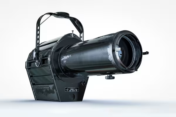 In the tutorial you create this 3D object with Cinema 4D R19.
You might also like

How it works. What options exist.

Edit films, transitions, animations, and more

Practical applications for companies

Produce high-quality videos
Comment now „Cinema 4D tutorial: Basics & 3D practice for beginners“