Before version 21, the design options for the bevels on the cover surfaces, also known as caps, were rather limited. Some standard curves could be set together with the desired radius.
Since version 21, we have considerably more freedom. A MoText objectwith three known letters will serve as a first example.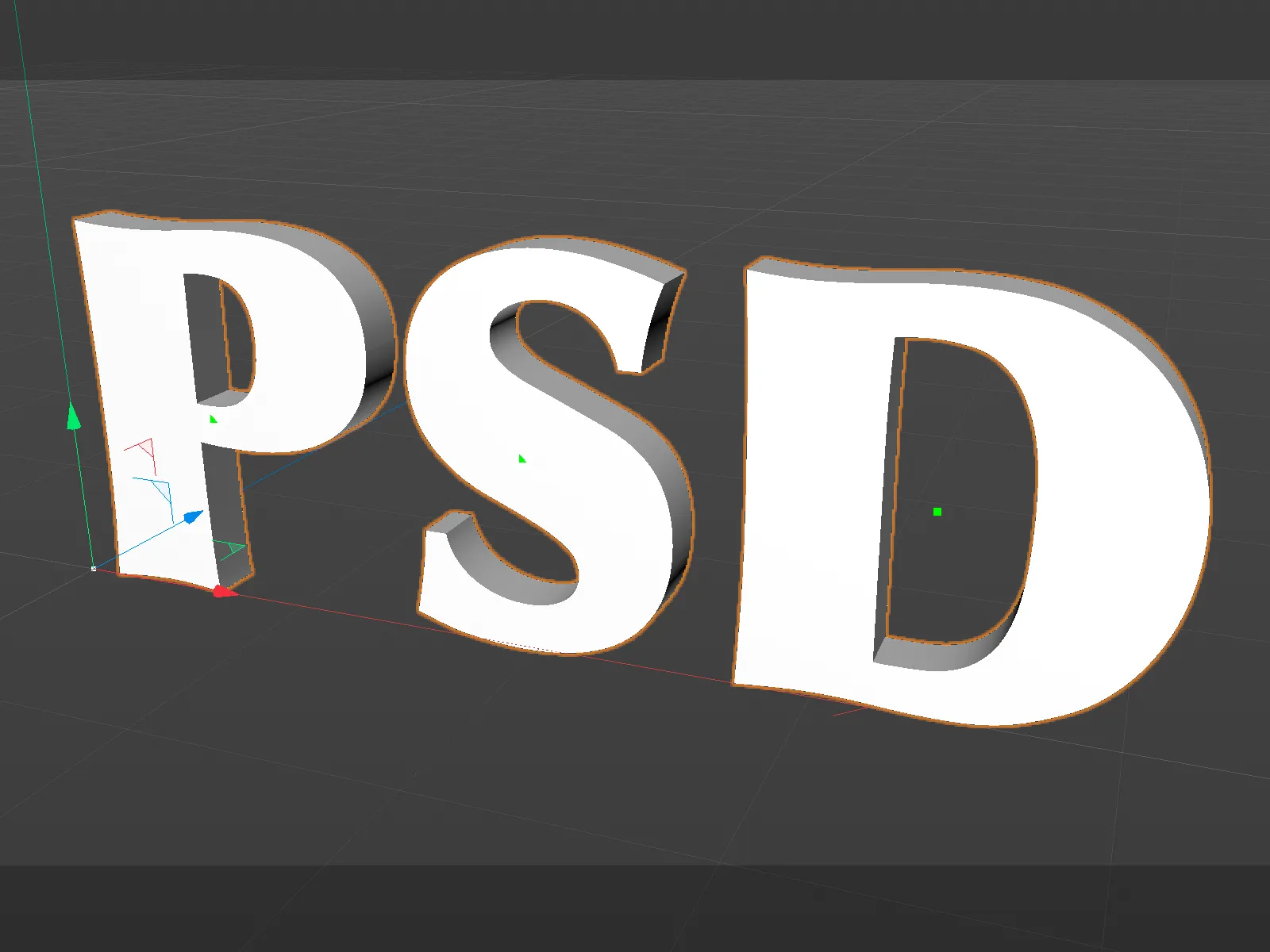
Setting the cover areas
The opacity pageof the MoText objecthas been extensively improved. First of all, we can decide whether we want cover areas on the front (start) and/or on the back of the object (end). Unlike in the previous version, the bevel settings for the start and end curves can be defined separately by activating the Separate bevel settings option.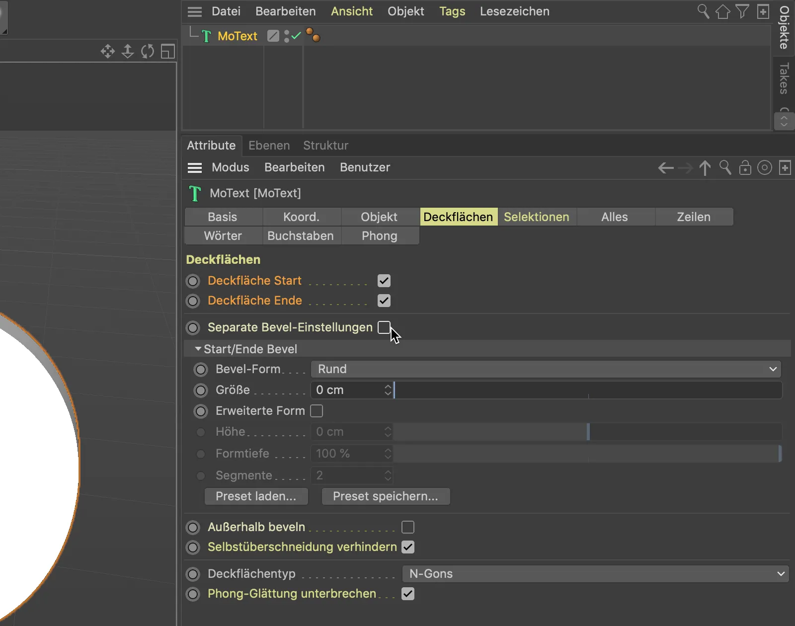
So that we can better assess the quality of the bevels in the following steps, we switch to the Gouraud Sharing (lines) mode via the Display menu of our 3D view.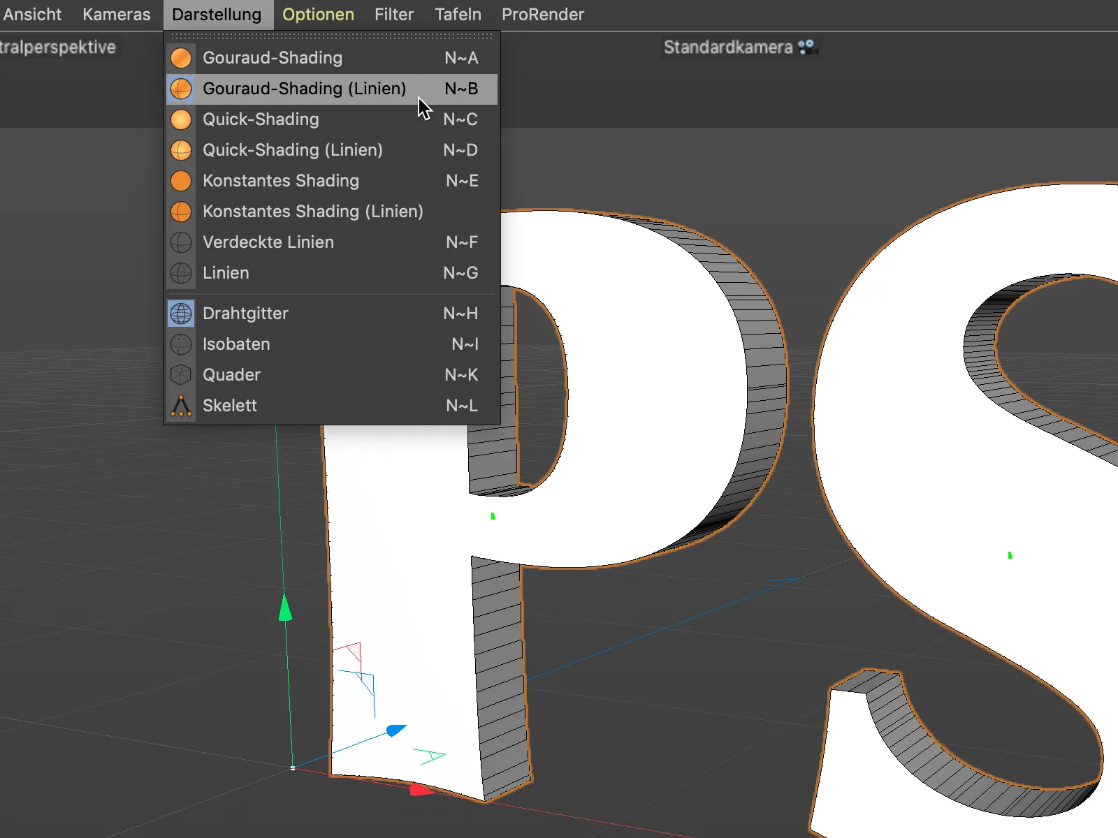
We will initially stick with the standard round bevel shape and create a bevel for our lettering using the Size parameter. As the cover area type N-Gons is selected further down in the settings dialog, we do not need to worry about subdividing the cover area any further.
Incidentally, there are also new, additional options for the subdivision of the cover areas to be discovered here, which could be interesting depending on the area of application.
I have reduced the number of segments for beveling to 1 to make it easier to understand.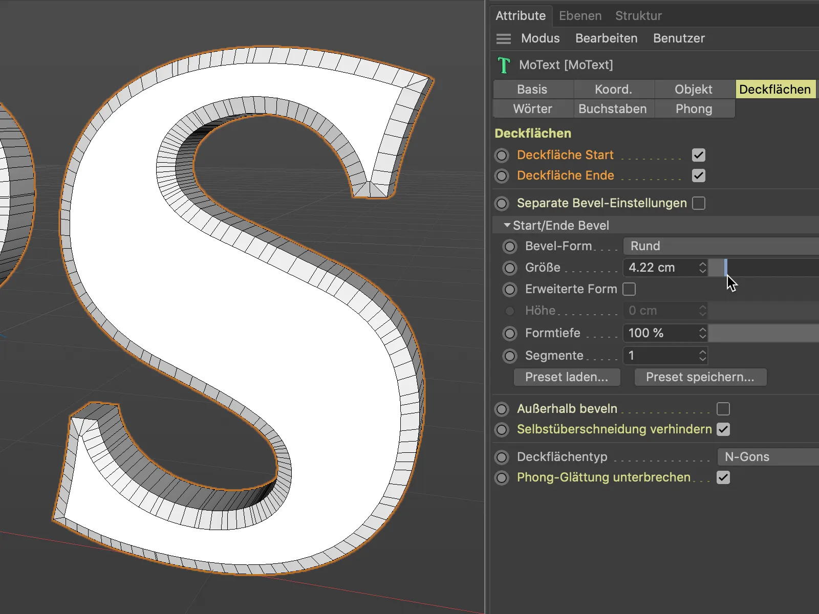
Even if we push the size parameter to its limits, we won't have any problems with overlapping bevel areas. This is ensured by the Prevent self-overlapping option, which is activated by default.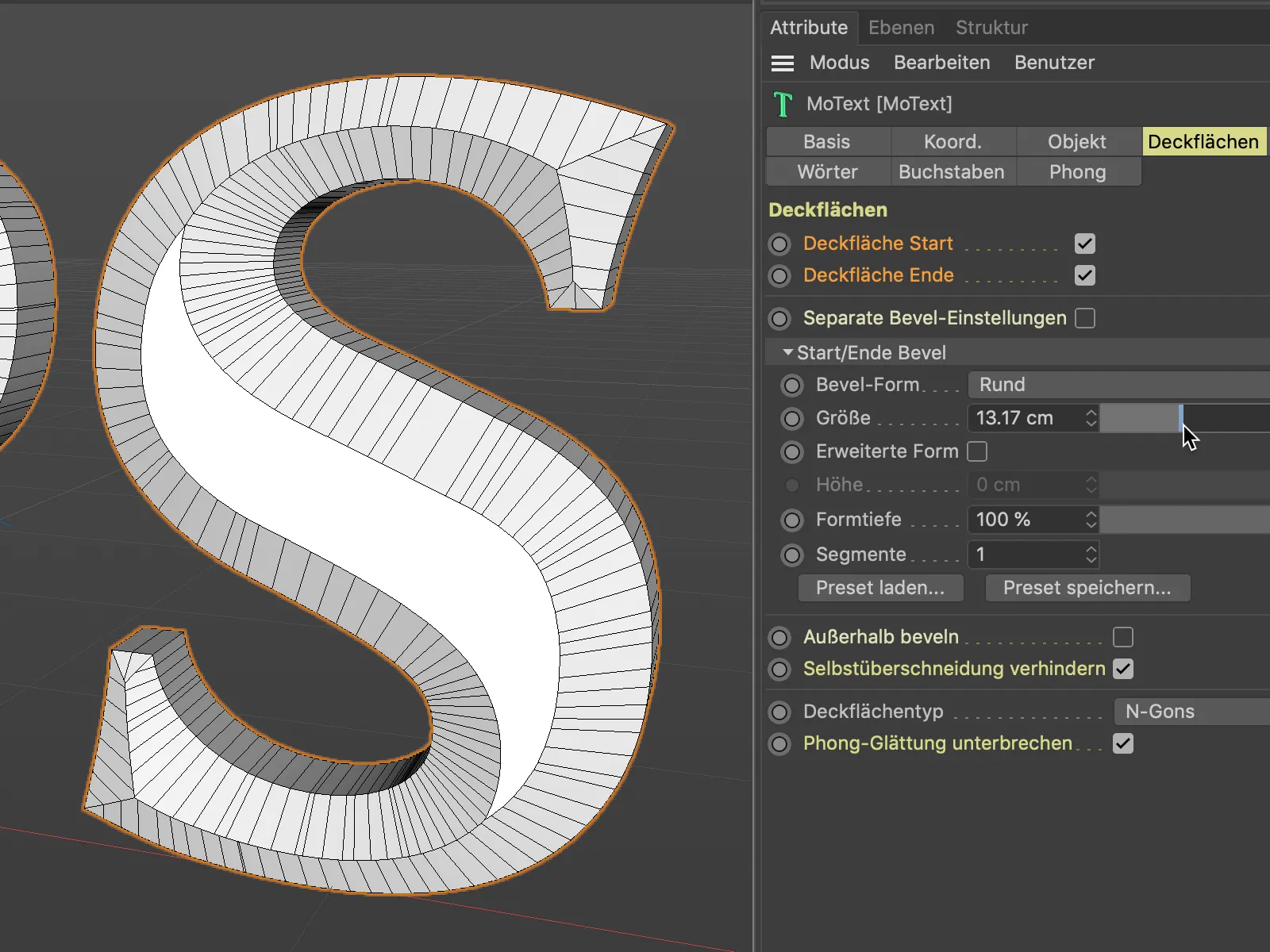
If we deactivate this option for a short time, we can see the problems that the new cover area and rounding functions save us from.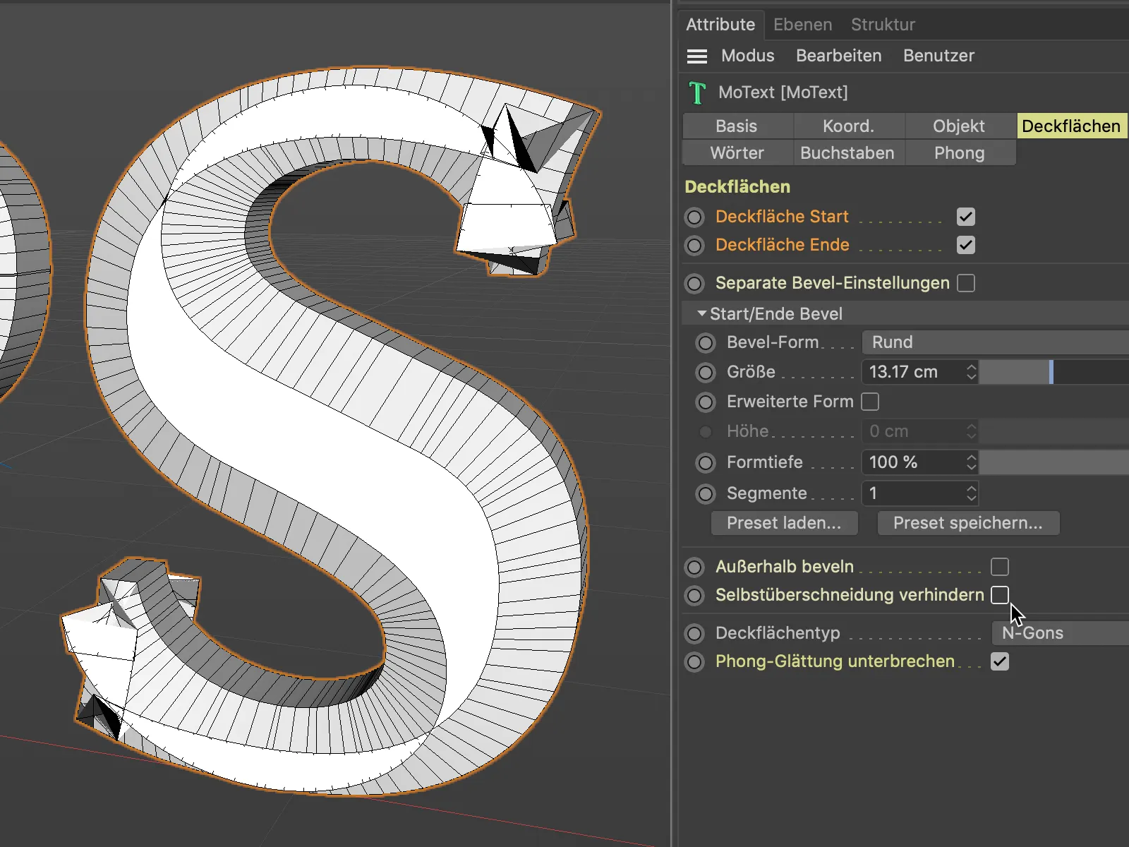
Round bevels already existed in the previous versions. Next, let's take a look at the other bevel shapes that are now available to us. With the Curve bevel shape, we have a free hand in the design.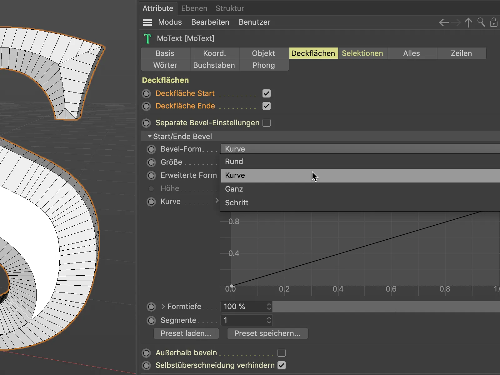
The Curve setting allows us to define the bevel shape using a spline curve. We set additional curve points as usual by clicking with the Ctrl keyheld down.
To ensure that the bevel curve has sufficient geometry for shaping, we need to increase the number of segments accordingly.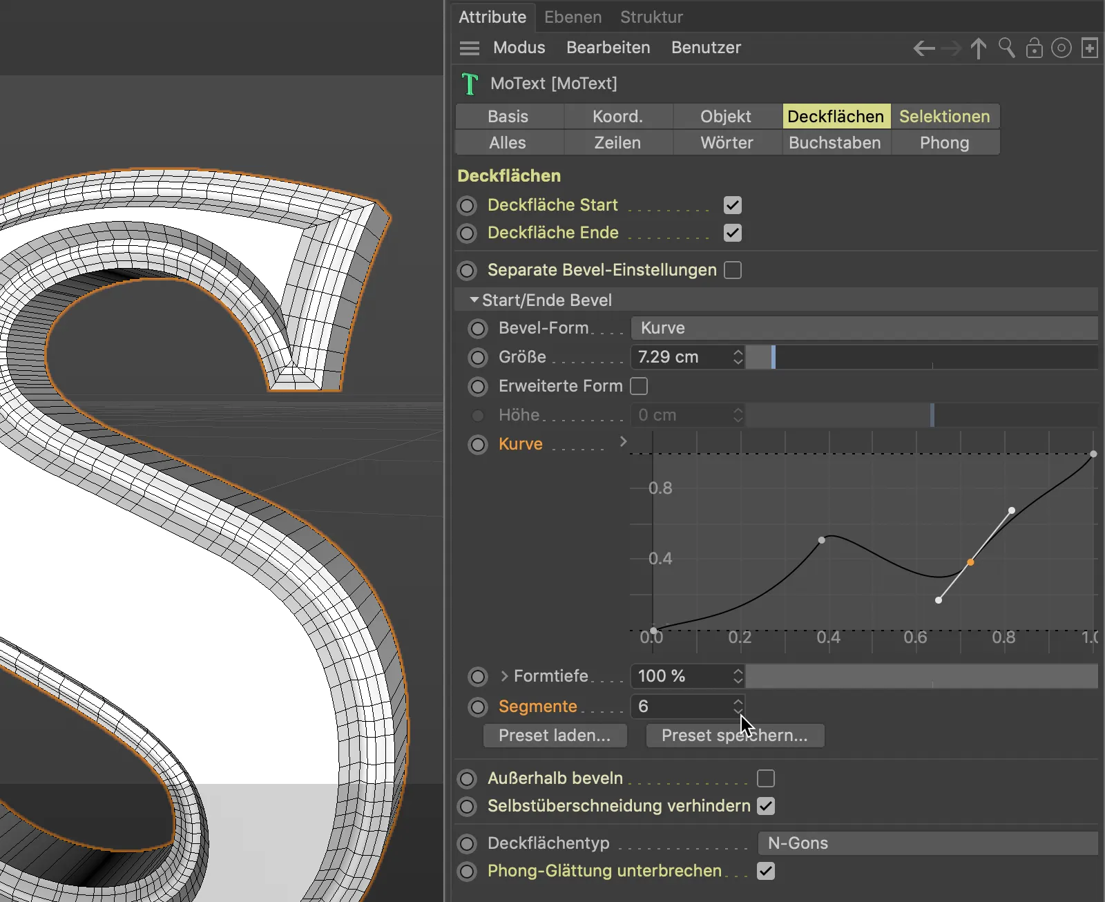
The Ganz bevel shape provides a targeted subdivision at the edges of the cover surface. This may be desirable if the objects are later rounded using the Subdivision Surface Generator, but the cover surface edges are to remain defined.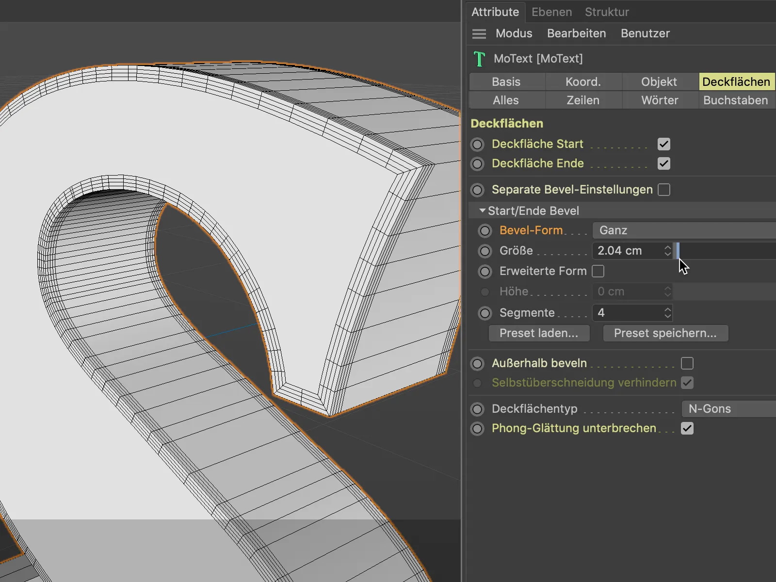
The bevel shape step works out the beveling step by step. The specified number of segments for the beveling is of course decisive for the number of steps.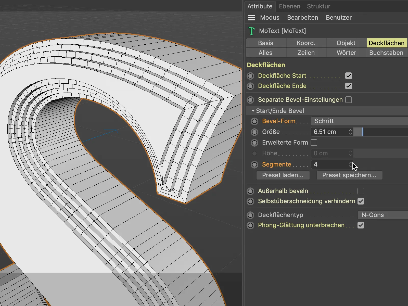
The Load preset... button provides a total of 16 ready-made bevel types including a meaningful preview for direct use. We can save our own creations for later use using the Save preset... button.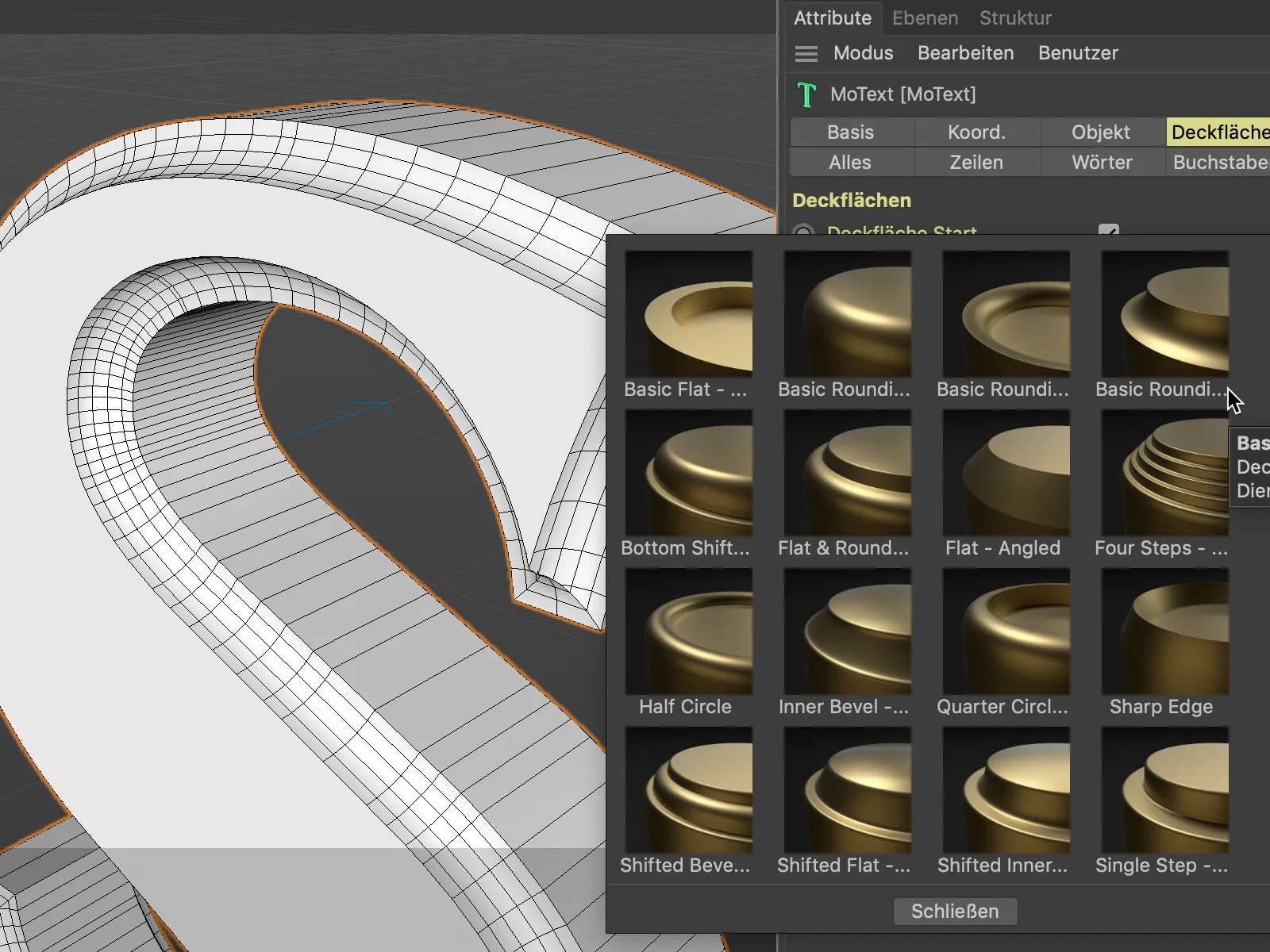
The bevels created so far have always been generated in the existing geometry. The depth of the text has therefore not changed as a result of the beveling. However, we can also generate the bevel as an extension of the existing geometry. For this comparison, I am using the bevel shape step with two segments.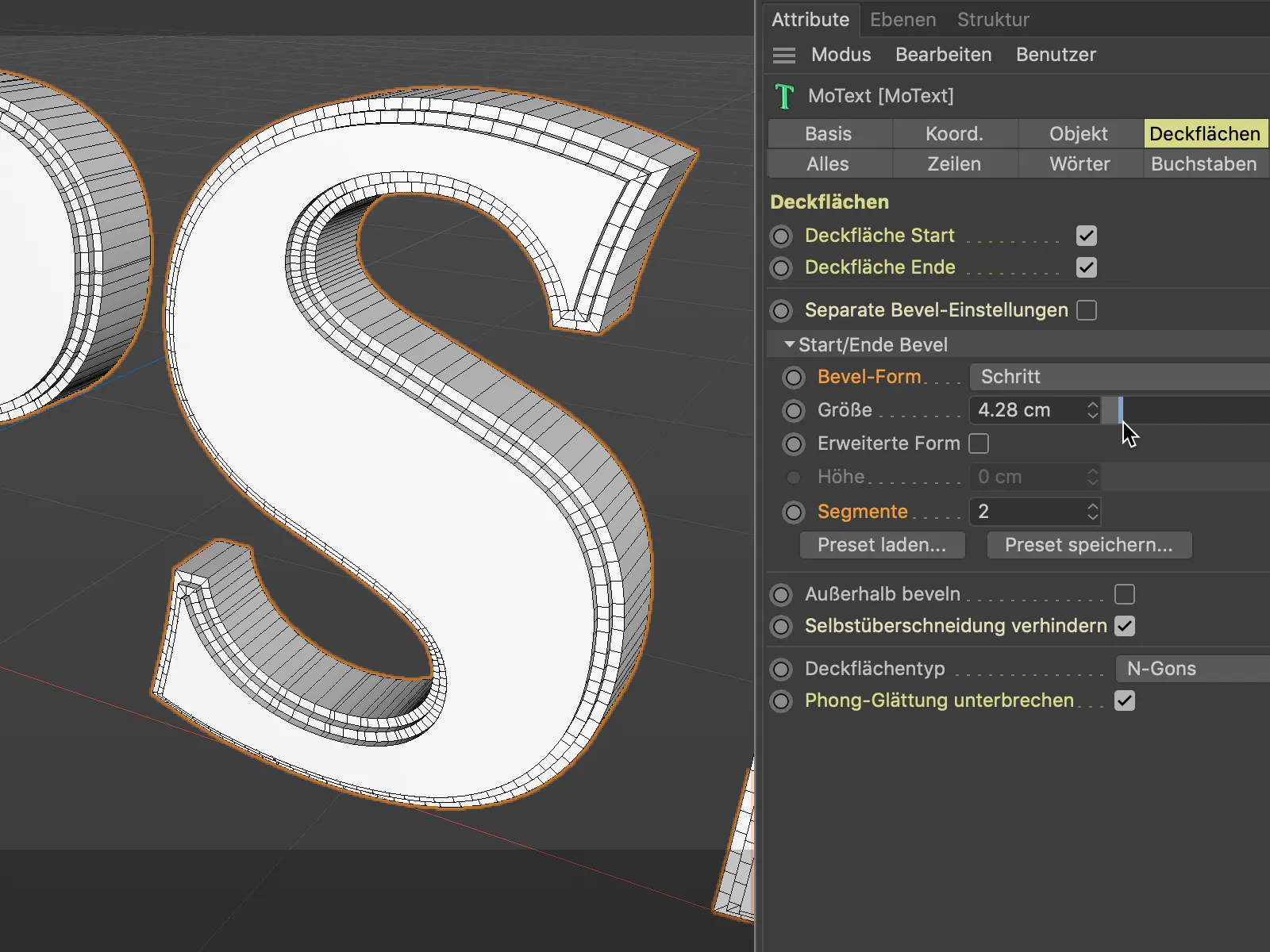
By activating the Extended shape option, we can now create the bevels in addition to the base object - with the spread specified under Height.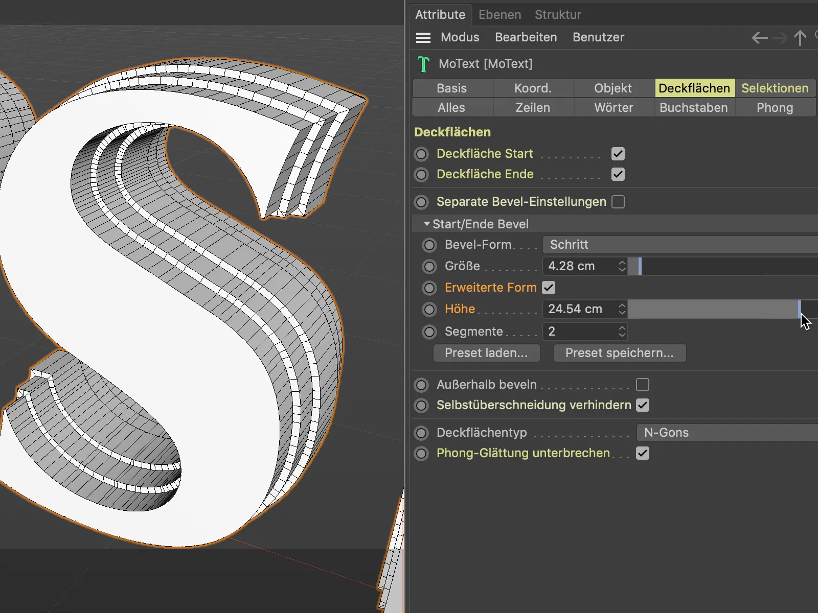
Using the selections for texturing
Spline or generator-based objects have their own selections for the hull, the cover surfaces and the associated bevels. This is not a new feature of version 21, as we were previously able to use the virtual selections in the texture tag for the targeted application of textures by specifying the abbreviations C1, C2, R1 etc., but not as a selection tag.
What is new in version 21, however, is that our work is made much easier by a separate Selections page in the settings dialog. All existing selections are neatly listed there.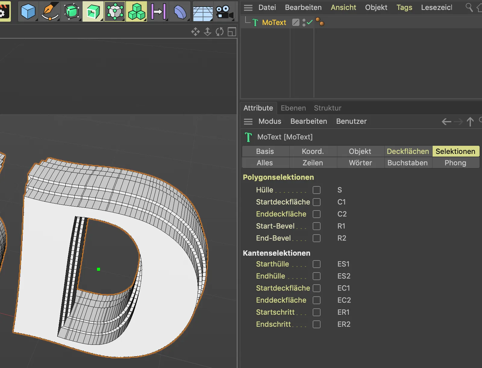
By activating the respective polygon or edge selection, we create the tags for the desired selections.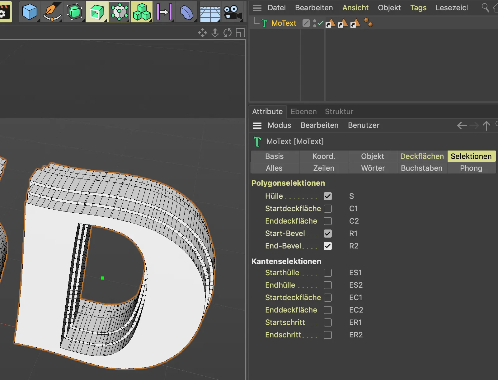
Unfortunately, the tags do not differ according to the type of selection, but by moving the mouse pointer over them, we can quickly see which selection tag we need to drag into the Selection field in the settings dialog of the material tag in order to restrict the material to this selection.
Incidentally, the material tag is identical to the texture tag, it just has a different name in version 21.
In my example, the MoText objectis assigned a blue base material and a red material is assigned for the untreated cover.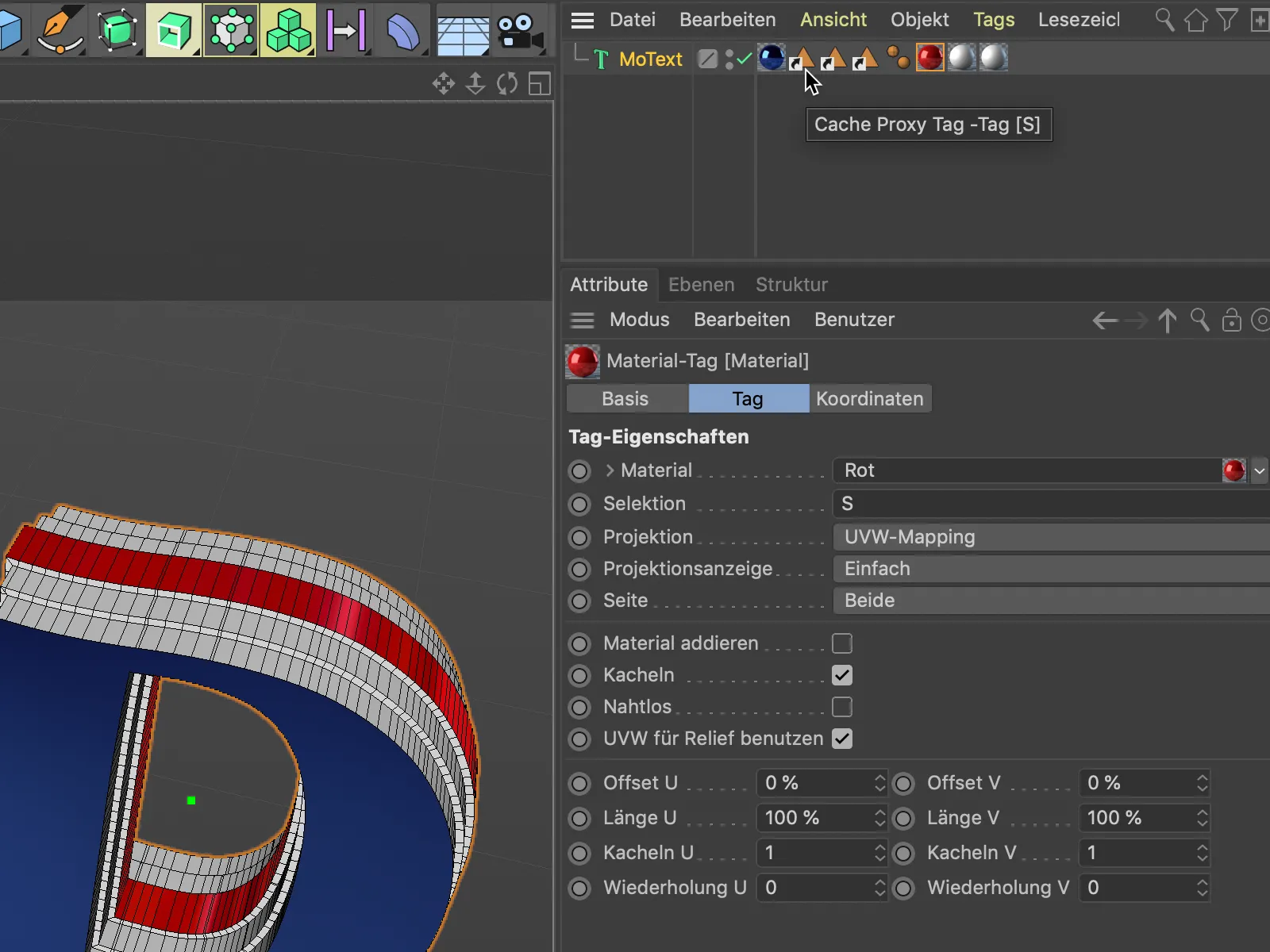
As the Selection field can only hold one selection at a time, the two bevels of the object, i.e. the selections R1 and R2, each require their own material tag with the corresponding selection.
This illustration clearly shows how the new cover surfaces and bevels are structured in Cinema 4D Release 21.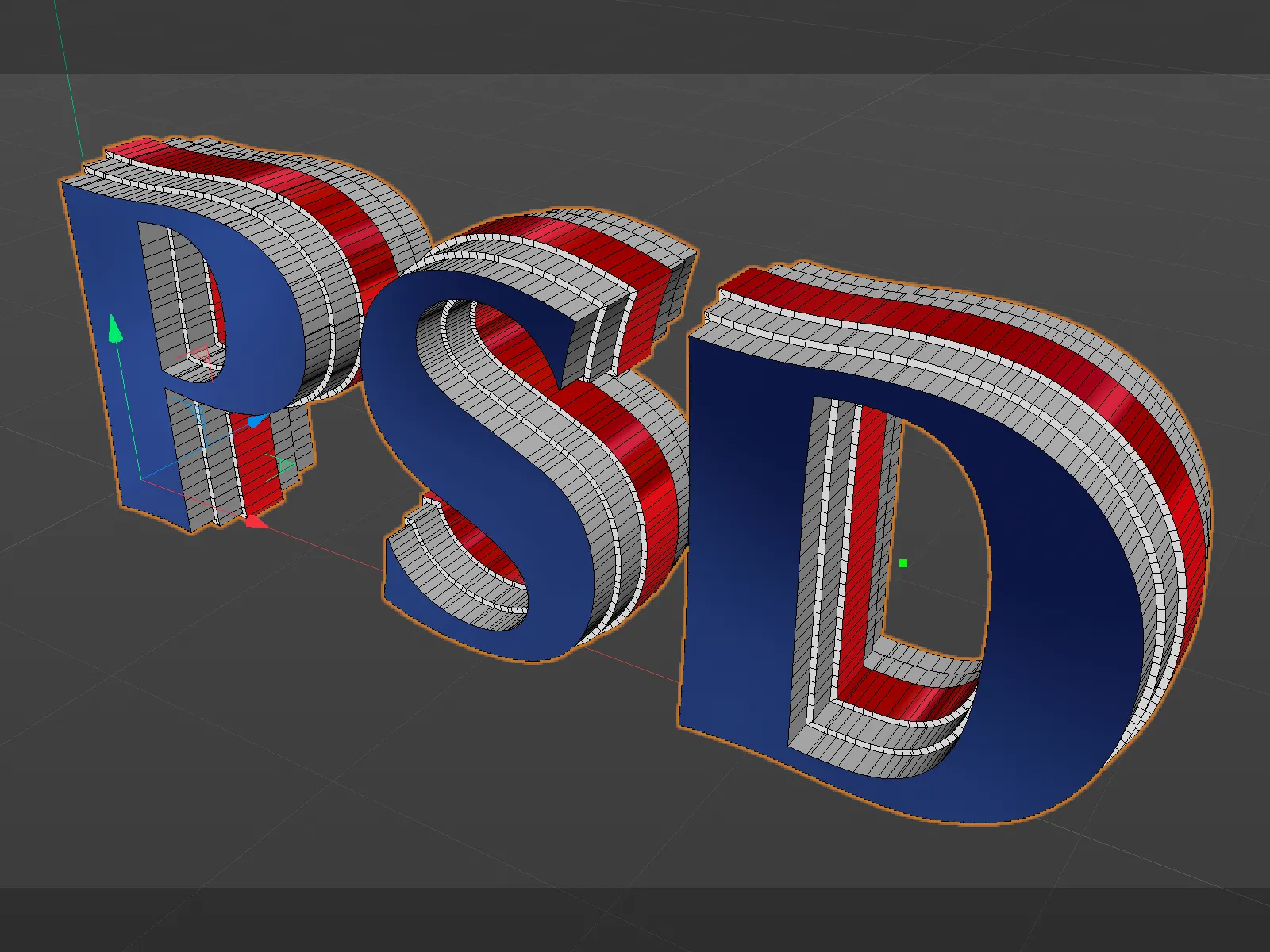
Negative bevels
For good measure, let's take a look at the example of a sweep objectto see how we can very easily design the ends or top surfaces of a spline-based object.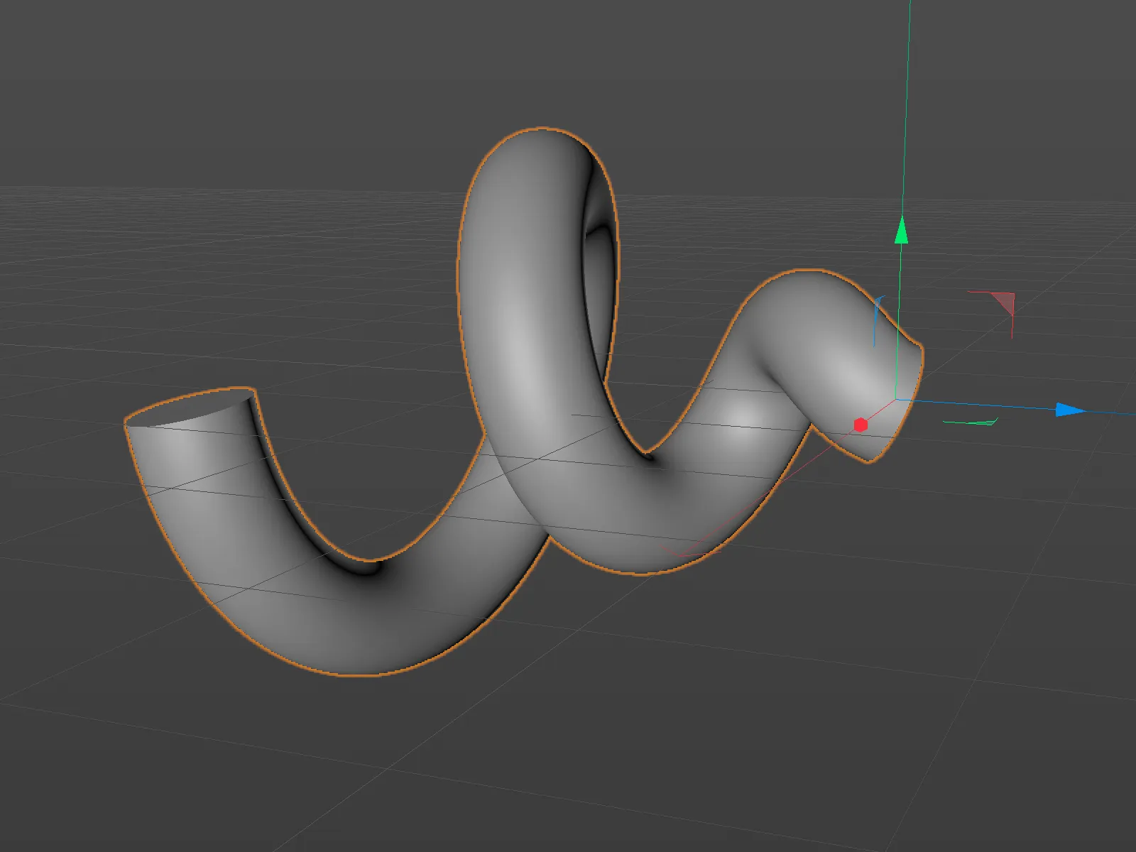
For this object, we can also find the cover and selection pagesin the settings dialog. We use the Load preset... button to call up the ready-made bevel shapes ...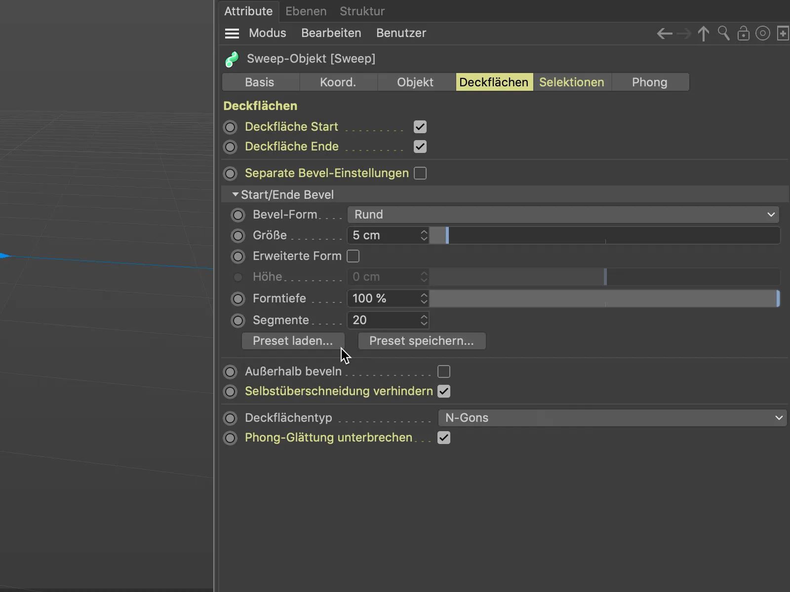
... and select a suitable basic shape.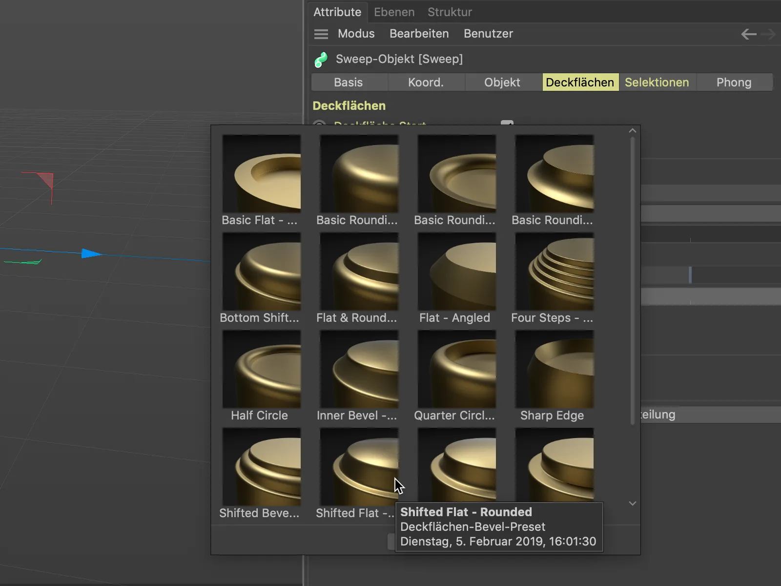
In order to be able to assess the quality and subdivision of the beveling, we switch on the Gouraud shading (lines) display via the Display menu of the 3D view if it is not active.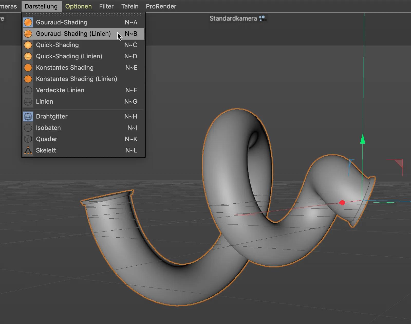
In contrast to the previous example, we now use a negative value for the size of the bevel shape, which we do not reach via the slider but have to enter in the corresponding value field.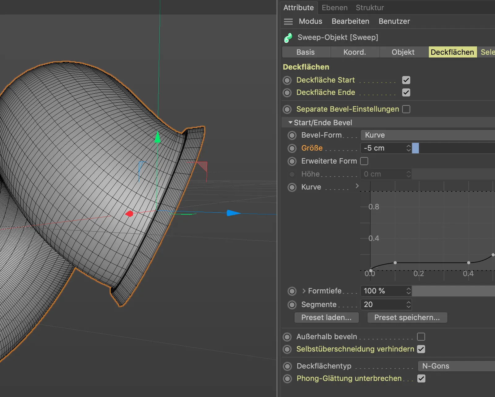
So that we can also control the extent of the bevel, we activate the Extended shape option.
The subdivision of 20 segments supplied with the preset is sufficient for our purposes. We now use the Height parameter to determine the width of this "negative" bevel.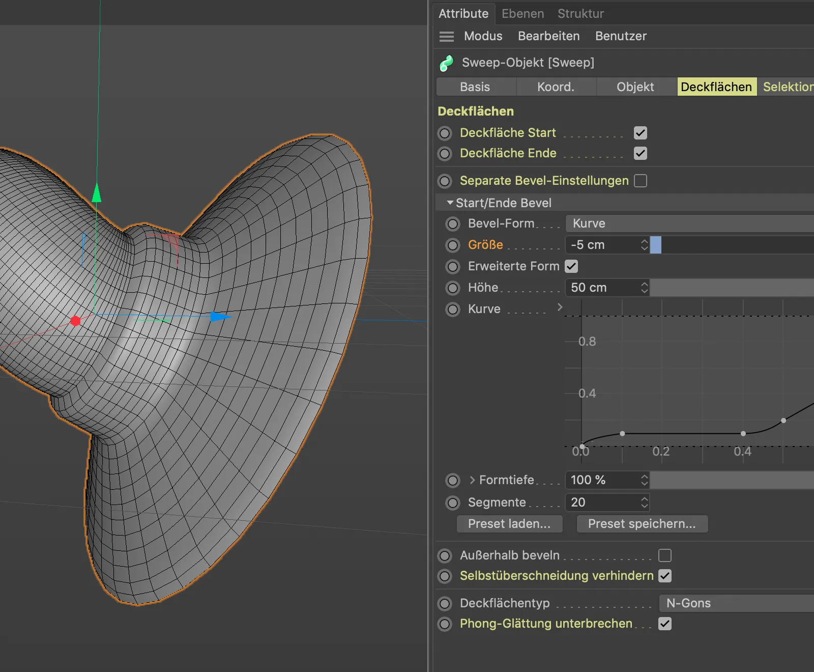
In this example, we also use the predefined selections to texture the sweep objectin a targeted manner. So that we can texture the hull and the bevels separately, we activate the corresponding three elements for generating the selection tags on the selections pageof the settings dialog.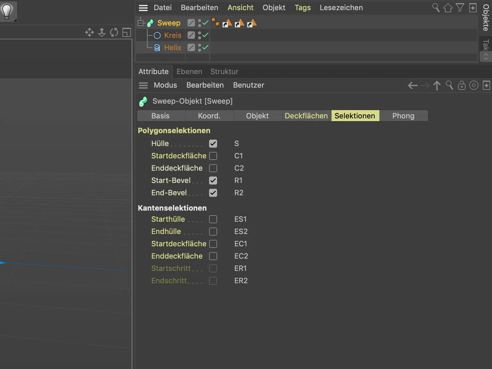
The shell of the sweep objectis assigned a blue material by dragging the selection tagfor the shell (S) into the Selection field of the material tag.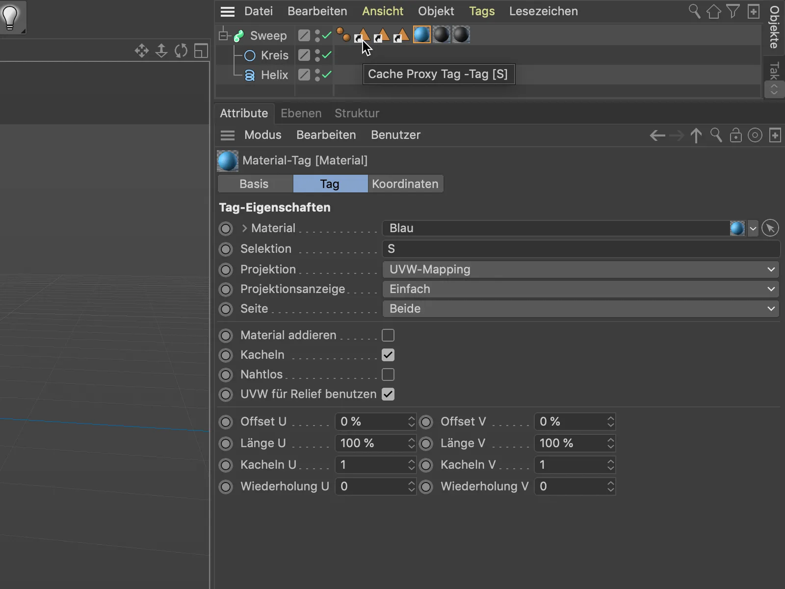
Because of the two selections (R1 and R2), two material tags with the respective selections in the Selection field are also required for the two ends or bevels of the sweep object.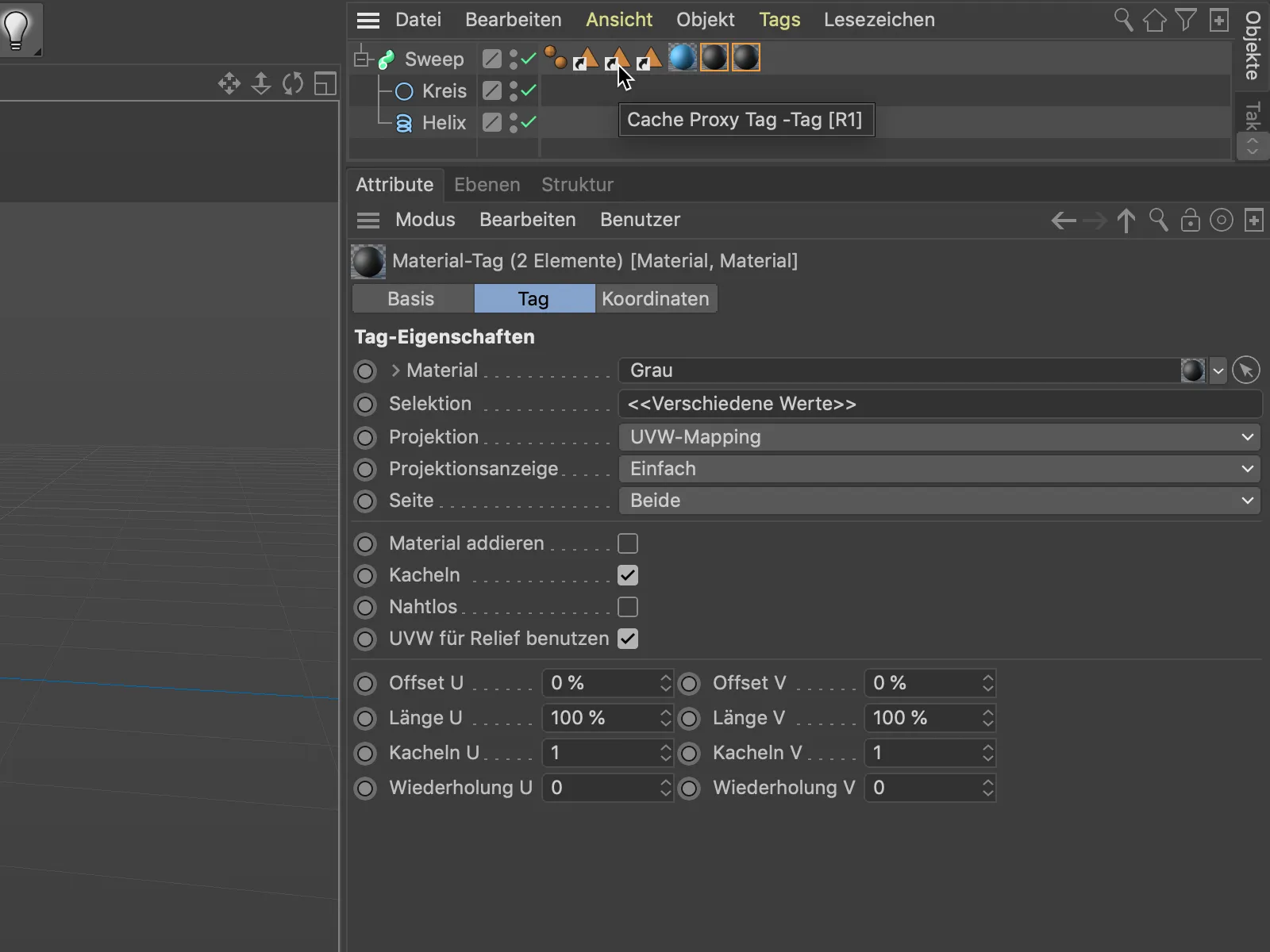
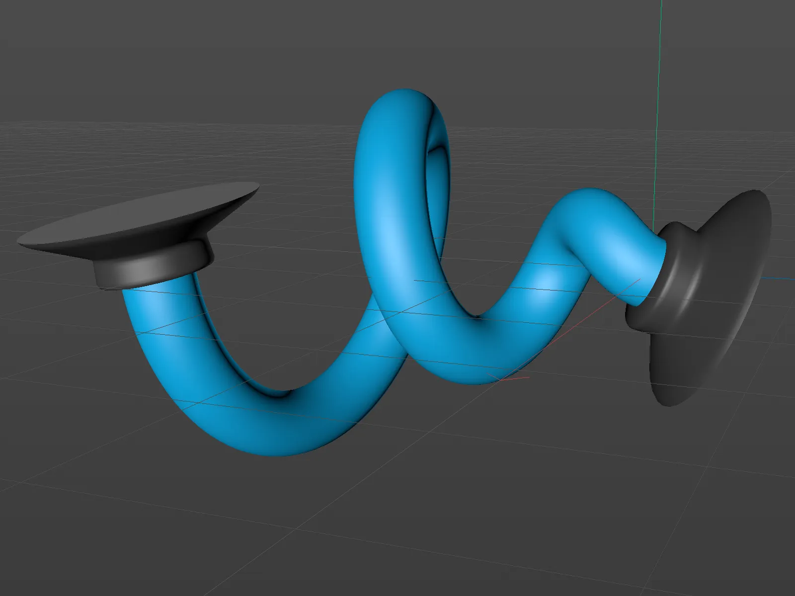
In this way, objects such as the now completed cable piece with the corresponding ends can be modeled and textured as a single, spline-based object with little effort.