So that we can concentrate on working with the new functions, I have prepared a project file in the package with the accompanying materials: PSD_R21_VectorVolume_start.c4d. It contains a parametric sphere objectand two particle emittersthat are directed at the sphere from above and below. The aim of this tutorial is for the emitted particles to hit the sphere and spread in all directions.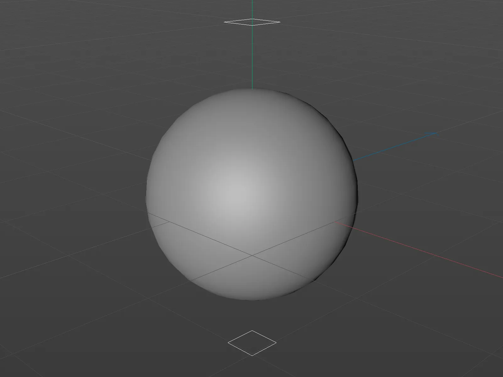
Let's take a quick look at the components of the scene. Both particle emittershave the same settings: They emit 500 particles up to frame 300, with a particle lifetime of 1000 frames, which lasts until the end of the animation length.
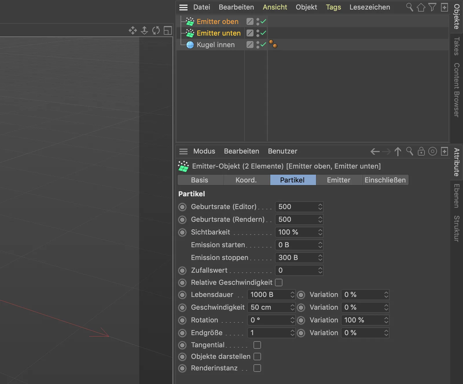
A click on the play button shows that the particles of both emitters are still moving through the sphere unimpressed at the moment. We want to change that now.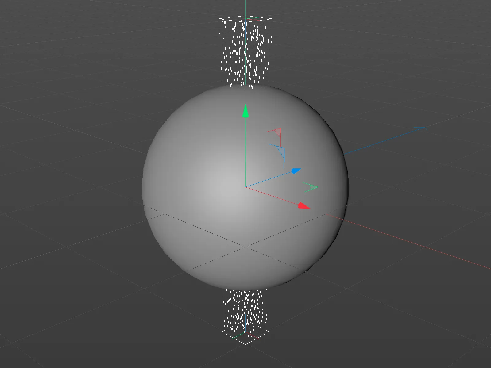
Creating the first vector field
We start by generating an initial vector field from the geometry provided by the sphere. It is intended to guide the impinging particles around the sphere in a random pattern.
To do this, we first get a volume generator from the Volume menu.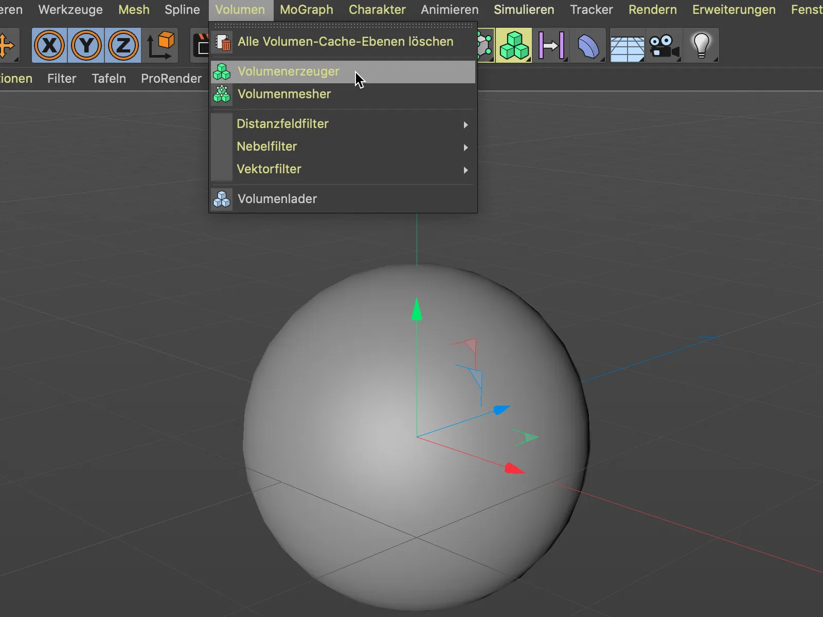
We then drag and drop the sphere objectinto the volume generator as a sub-object via the Object Manager. At the moment, the distance field is still specified as the volume type, which is why the volume generatoris currently still building our sphere from voxels.
To turn the sphere into a vector field instead, we simply change the volume type to vector via the corresponding menu.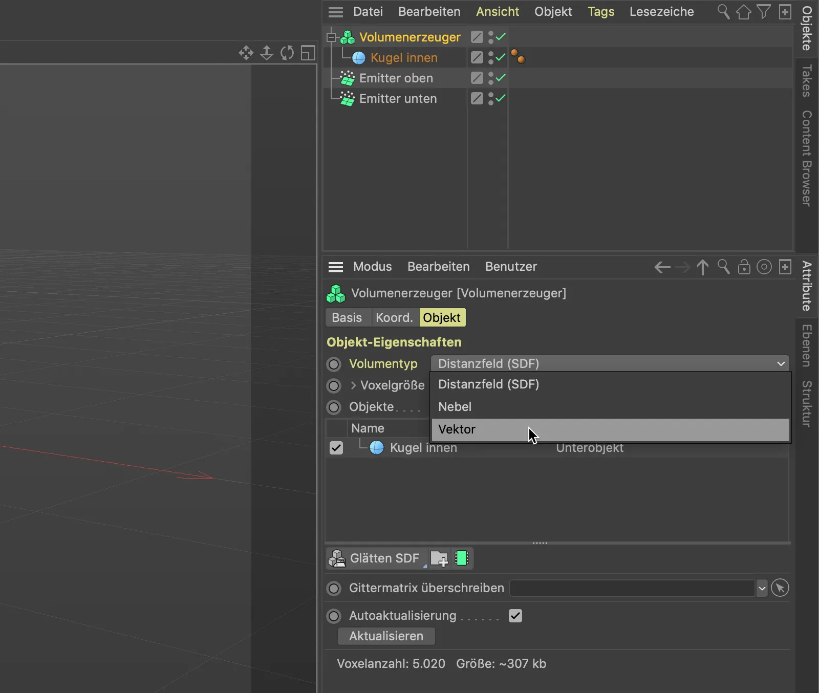
We now change the still somewhat coarse subdivision of the vector field via the voxel size. A value of 5 cm is completely sufficient for our purposes.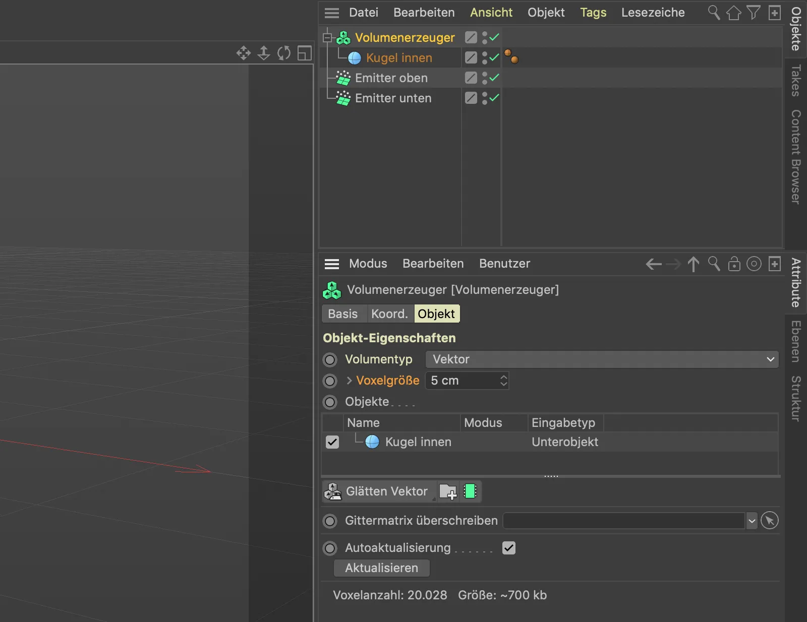
Thanks to the volume mesher, our former sphere objecthas now become a radial field of countless vectors.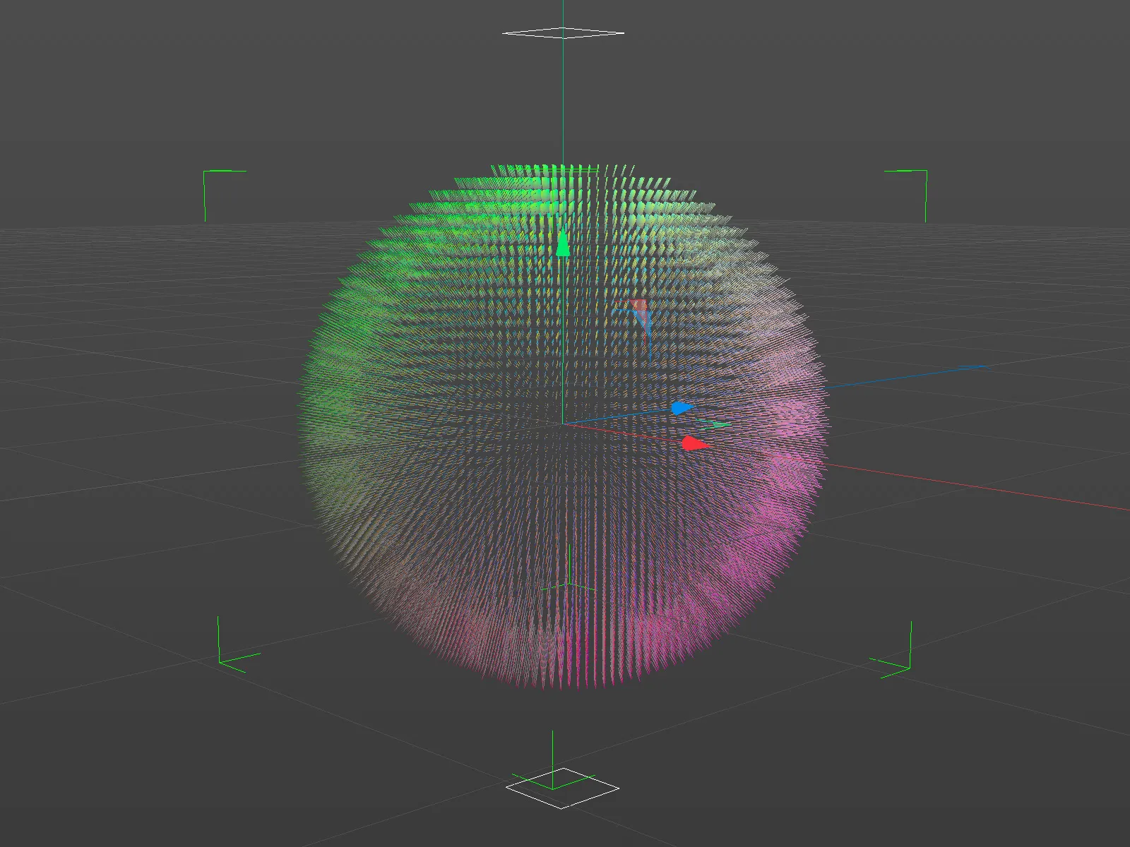
If we zoom in a little closer to the vector field, we can see the individual vectors, all of which are perpendicular to their position on the surface of the sphere. The resulting forces therefore all point away from our sphere. Not really what we need for redirecting the particles around the sphere.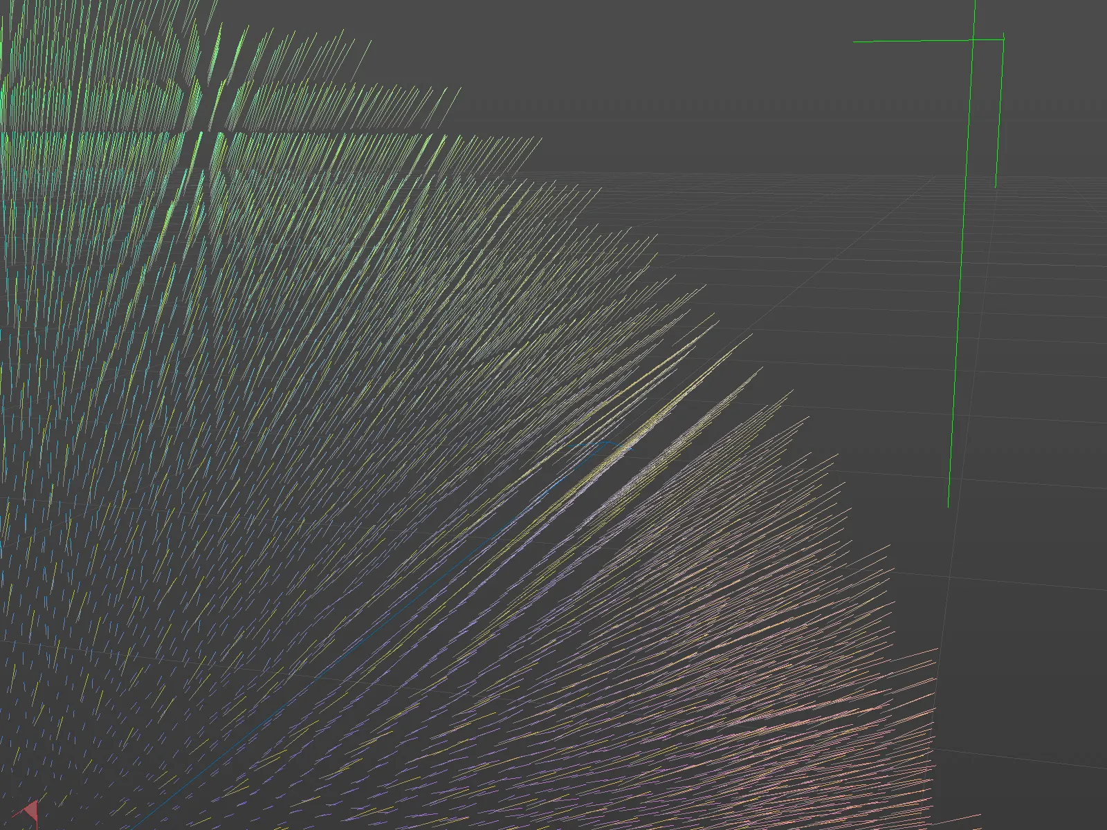
So we have to take care of two things: The vectors must be parallel to the surface of the sphere and also have a random pattern so that the particles on the surface are redirected in a wide variety of directions.
The random pattern is provided by a random field, which we bring into our scene via the Create>Field menu.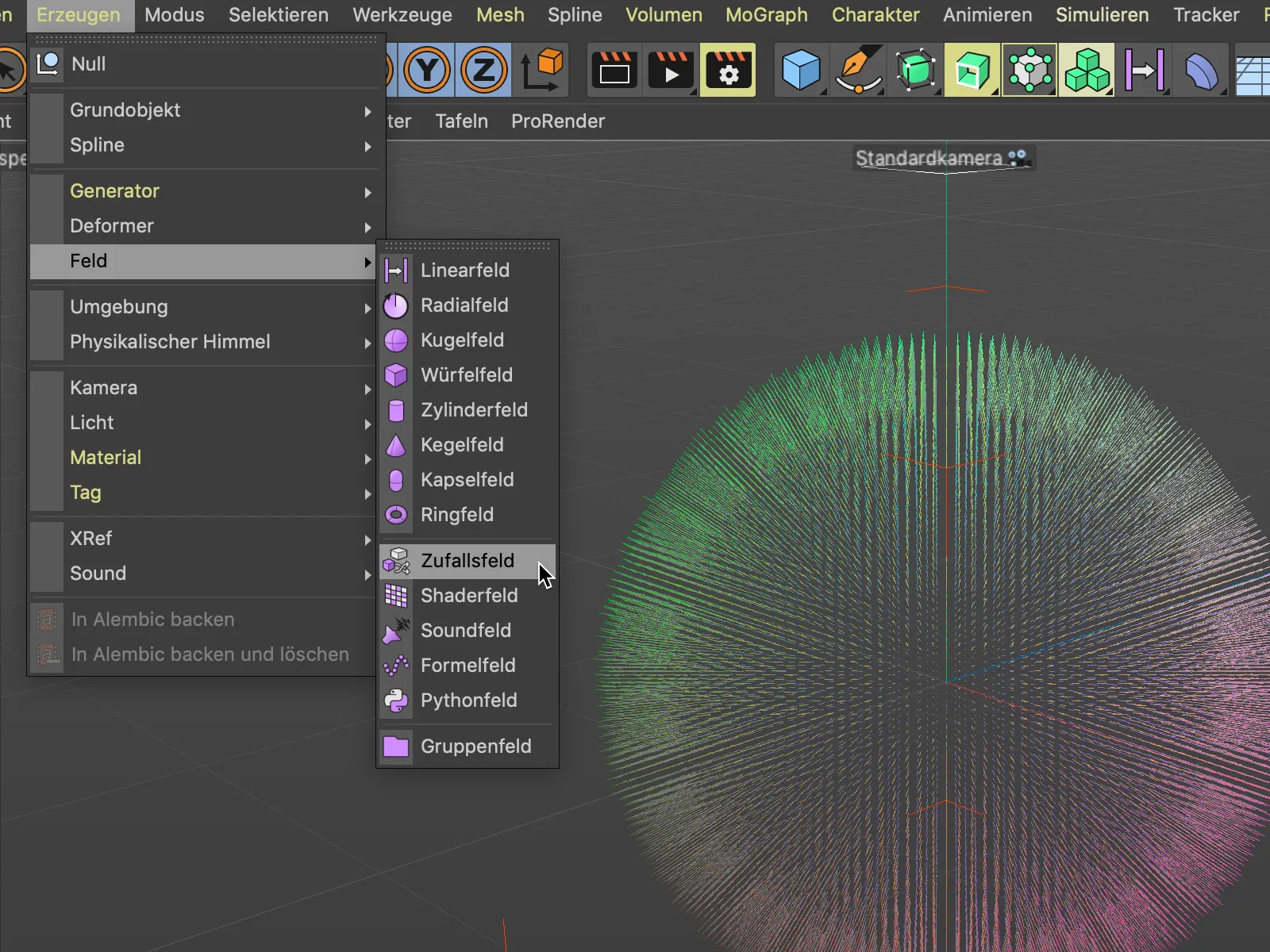
We drag and drop the random field into the volume generator as a sub-object via the object manager. In the settings dialog of the volume generator, the random field is then listed as a layer above our sphere.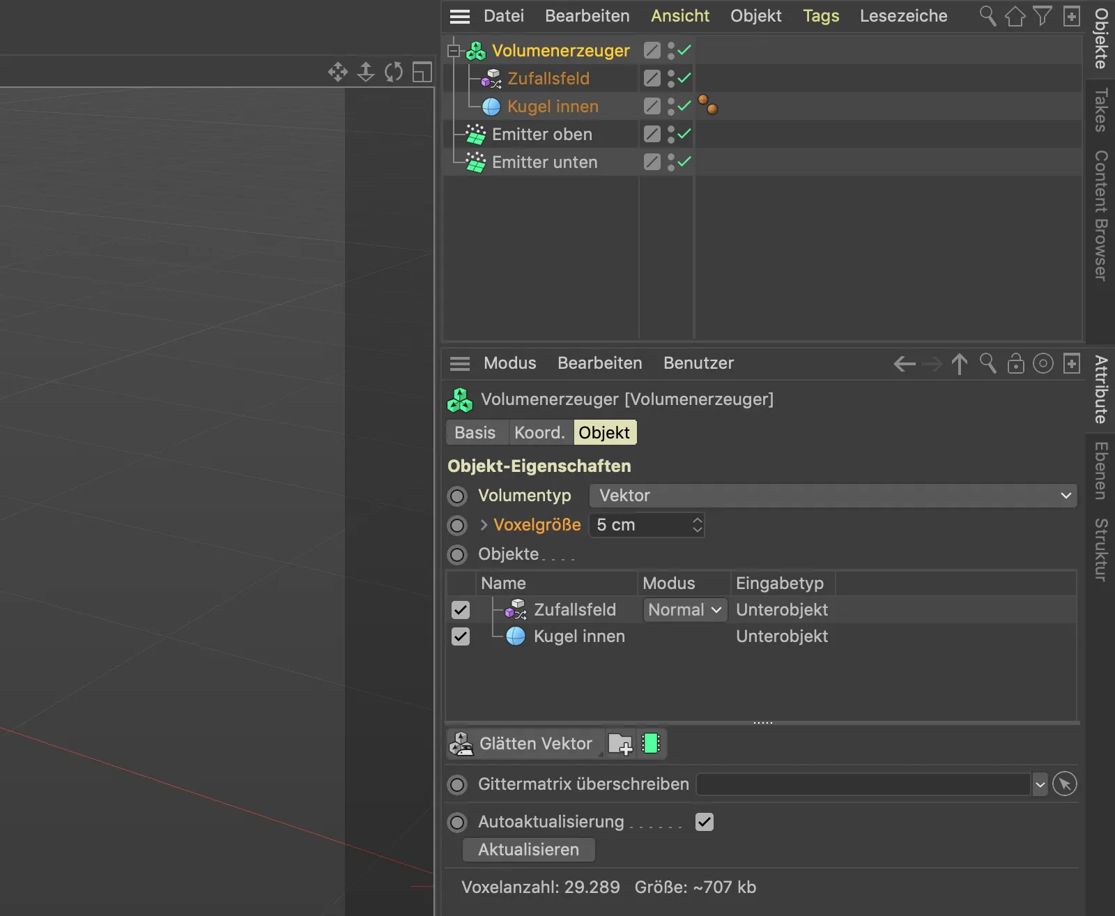
A look at the 3D view shows that the two vector fields are not yet working as we need them to. After all, the random field should act on the vector sphere below it in the list.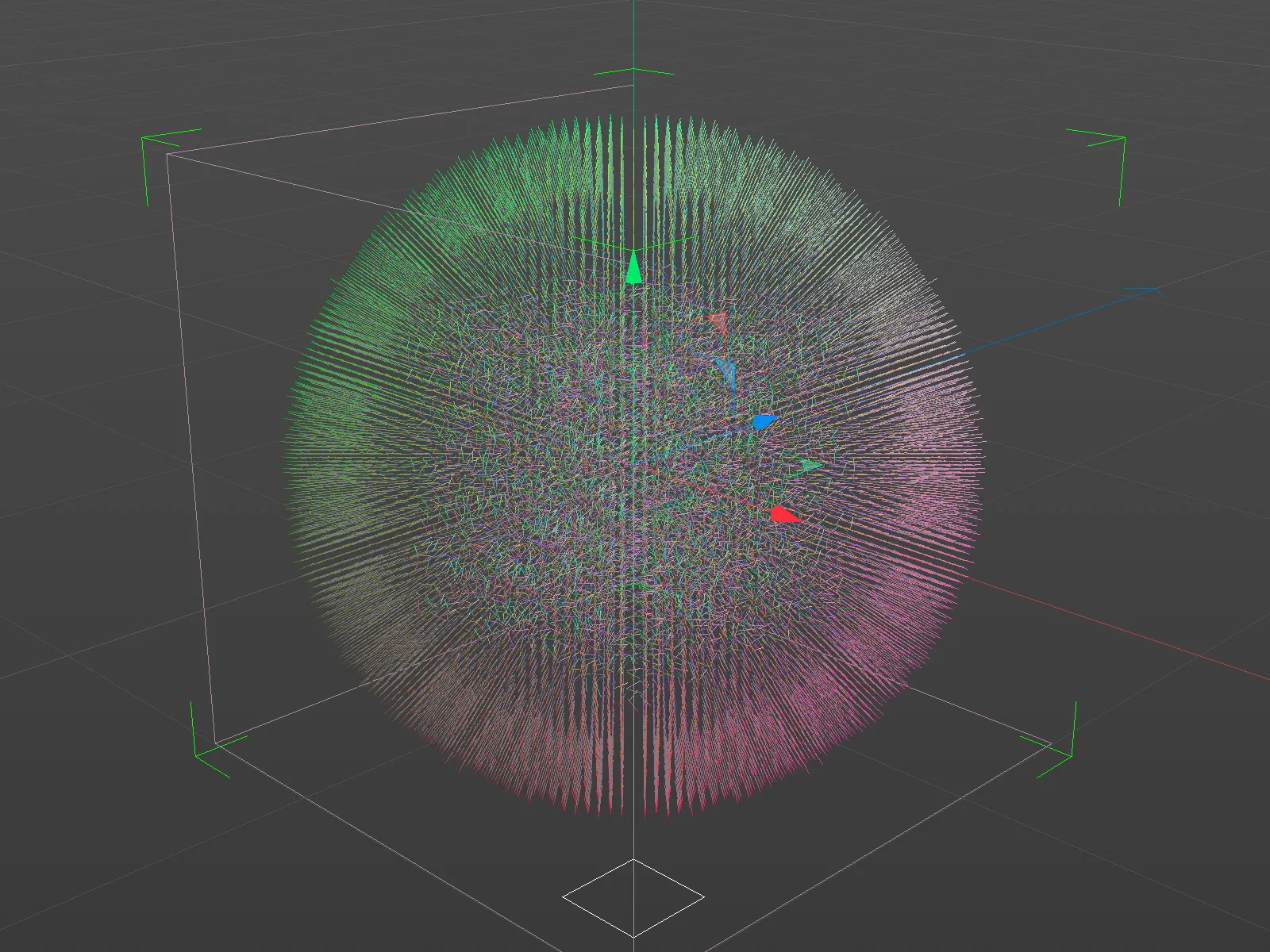
To achieve this, we select the entry for the random field in the list of objects in the volume generator and set the creation space to Objects in front of it in the settings for the random field below.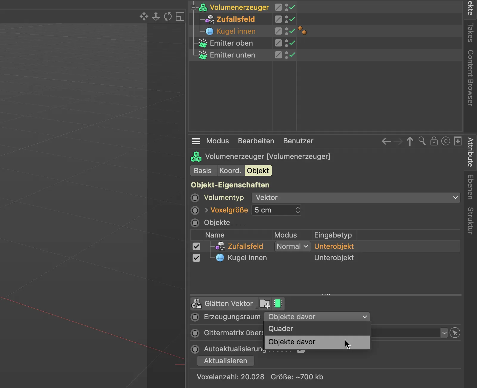
Now the random field affects all vectors provided by the sphere as desired. Now we only need to ensure that the chaotically twisted vectors point along the surface of the sphere.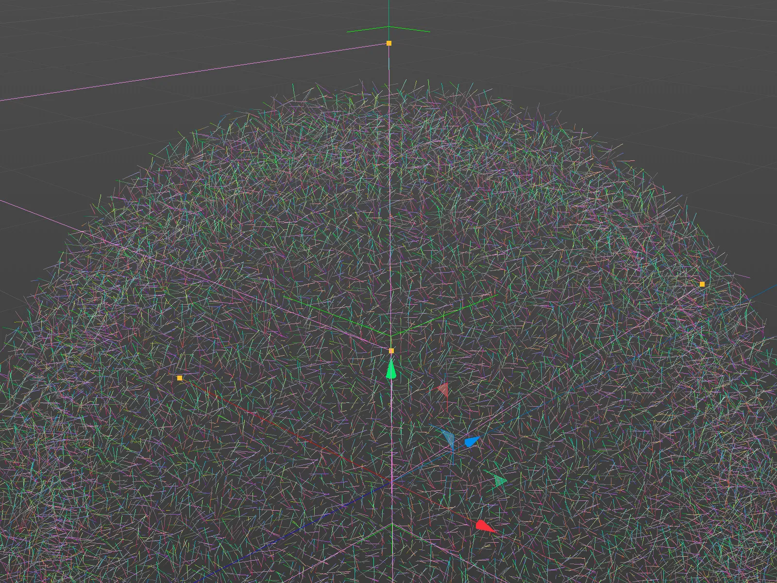
The calculation mode of the random field and the sphere does not seem to fit quite right yet. Using the mode menu in the object list, we select the cross calculation method for the random field. This mode is precisely designed to determine the perpendicular to two vectors calculated with each other using the cross product.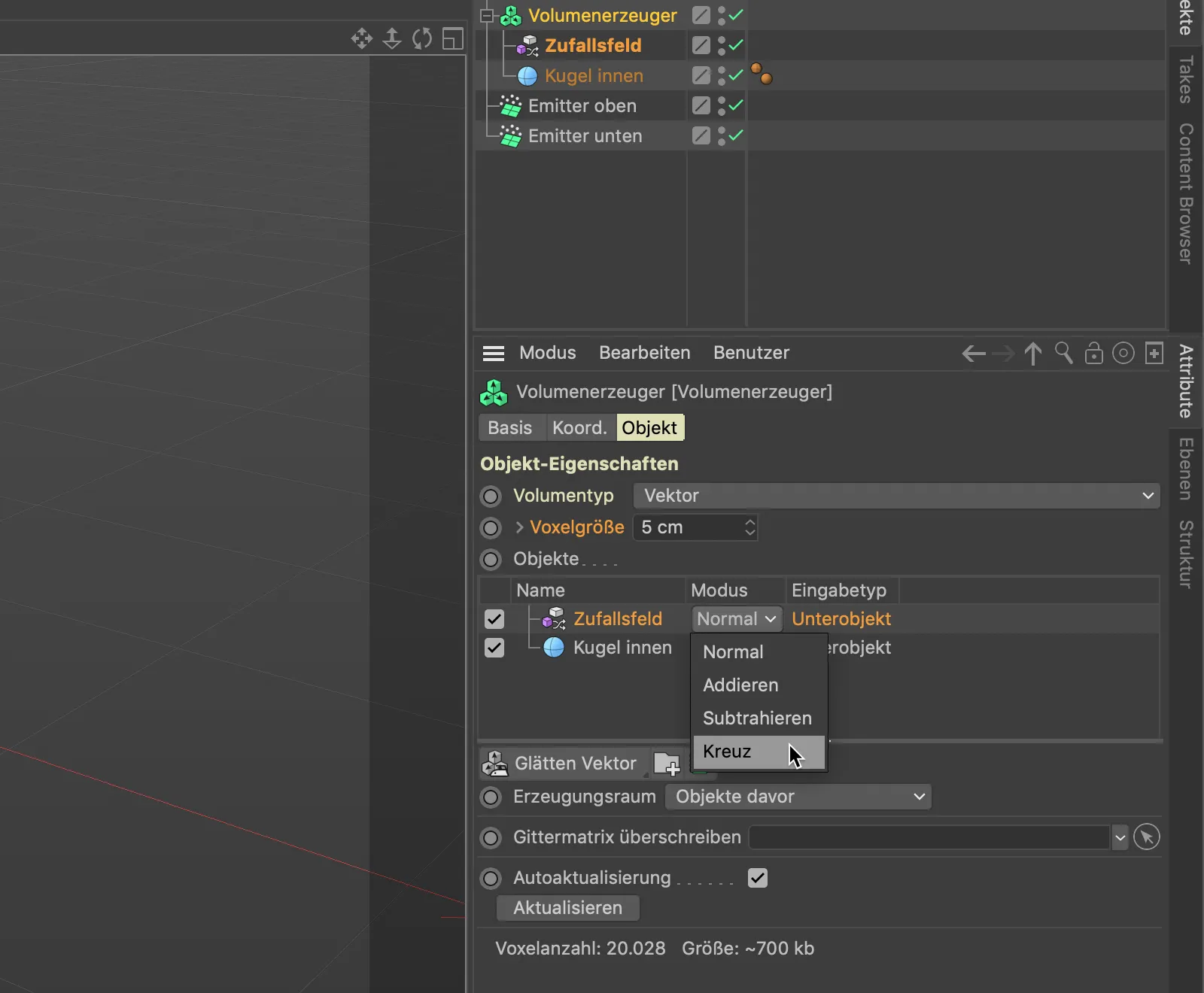
As a glance at our 3D view shows, the vectors run tangentially around our sphere as desired after this step.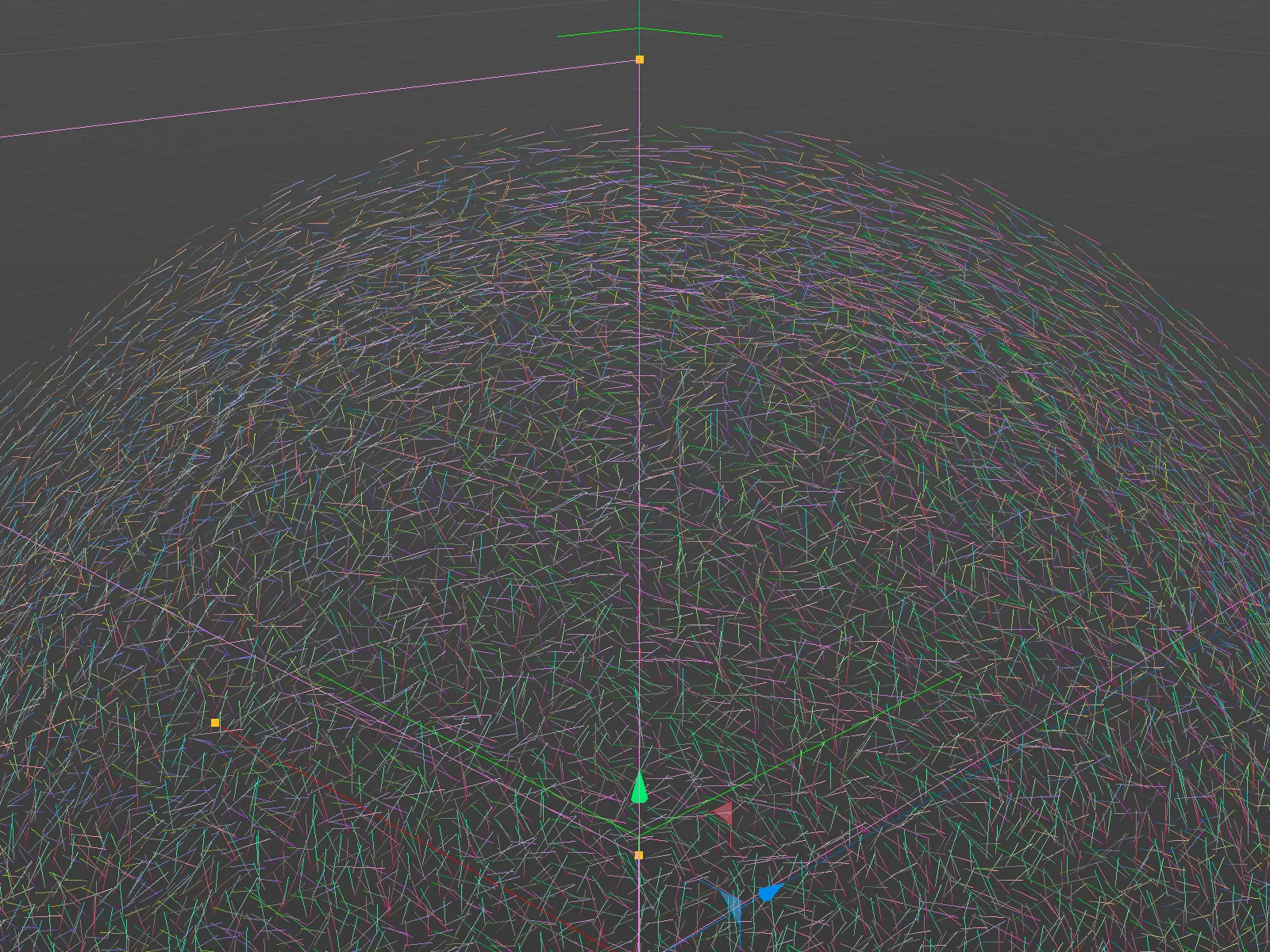
Using the force field
We have now prepared the first vector field for the path of the particles around the sphere, but unfortunately the particles have not yet taken any notice of our vectors.
In order for the vectors of our self-generated field to act as forces, we need a so-called force field object. We can find it in the Simulate>Forces menu.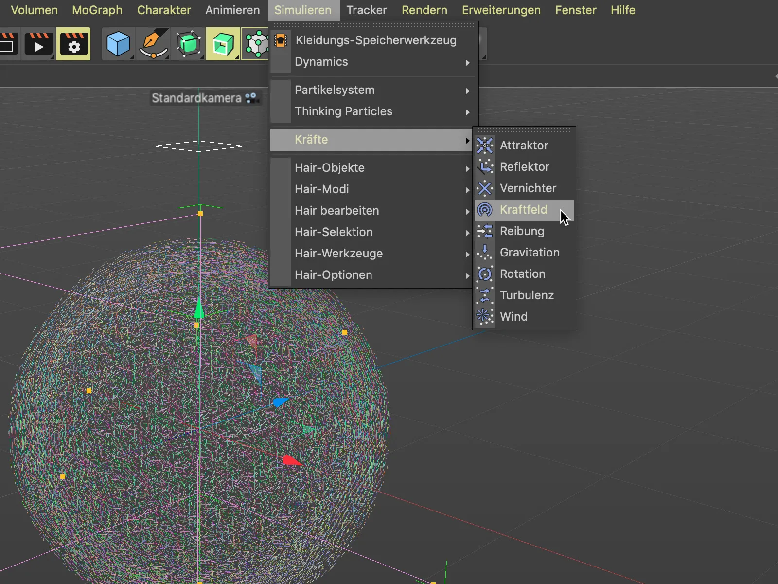
To make our vector volume act as a force field, we open the force field settings dialog and drag and drop the volume generator into the object fieldof the force field objectvia the Object Manager.
As soon as we let go, we are asked via a small selection menu whether the volume generator should be treated as a point or volume object. We naturally select the volume object option.
Our vector volume defined by the volume generator should now appear as an entry in the list of force fields. As we can see, the force field also works via layers and calculation modes, which gives us an idea of the new possibilities with the force field object.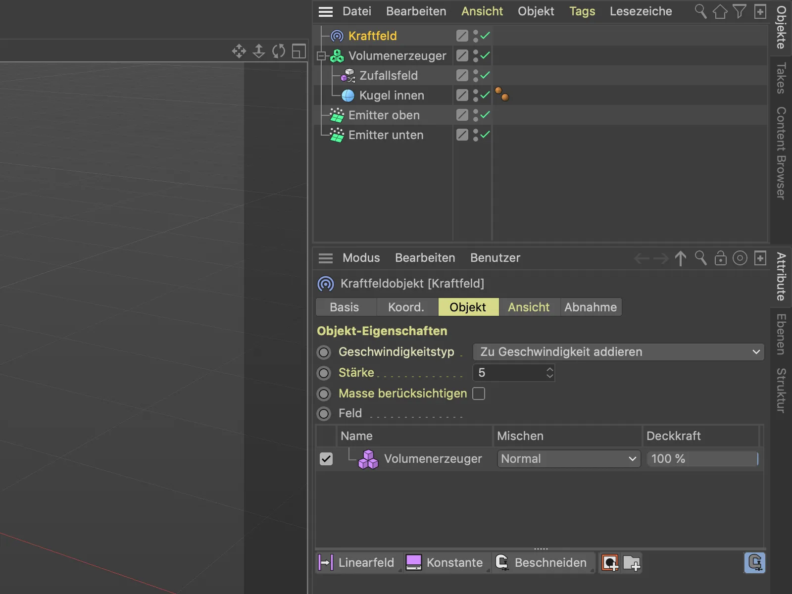
If we now start the animation using the play button, we can see that the particles are now influenced by our vector field.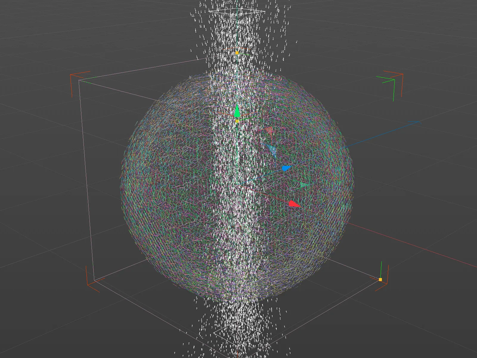
This is not quite the desired result yet. At the moment, the velocity type Add to velocity is still active in the force field object, so the particles are only deflected with a little more momentum. However, we want the particles to change their direction according to the vectors, which we select accordingly in the Velocity type menu.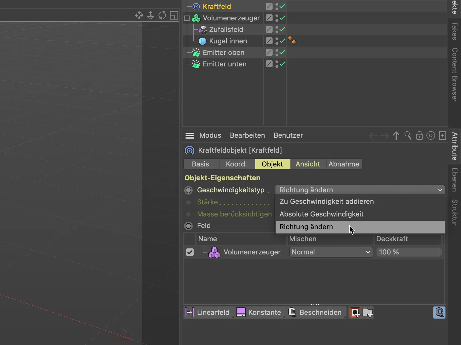
After this change, the animation already looks better. Many particles already find their way across the surface of the sphere, but some others are deflected away from the sphere. It is also noticeable that these deflected particles move along very strange paths.
We can fix the latter very easily by selecting the volume generator in the object list in the settings dialog of the force field objectand setting the sample mode from Next to Linear in its settings on the Layers page. This means that instead of simply rounding up or down to the next voxel, a linear mean value is used.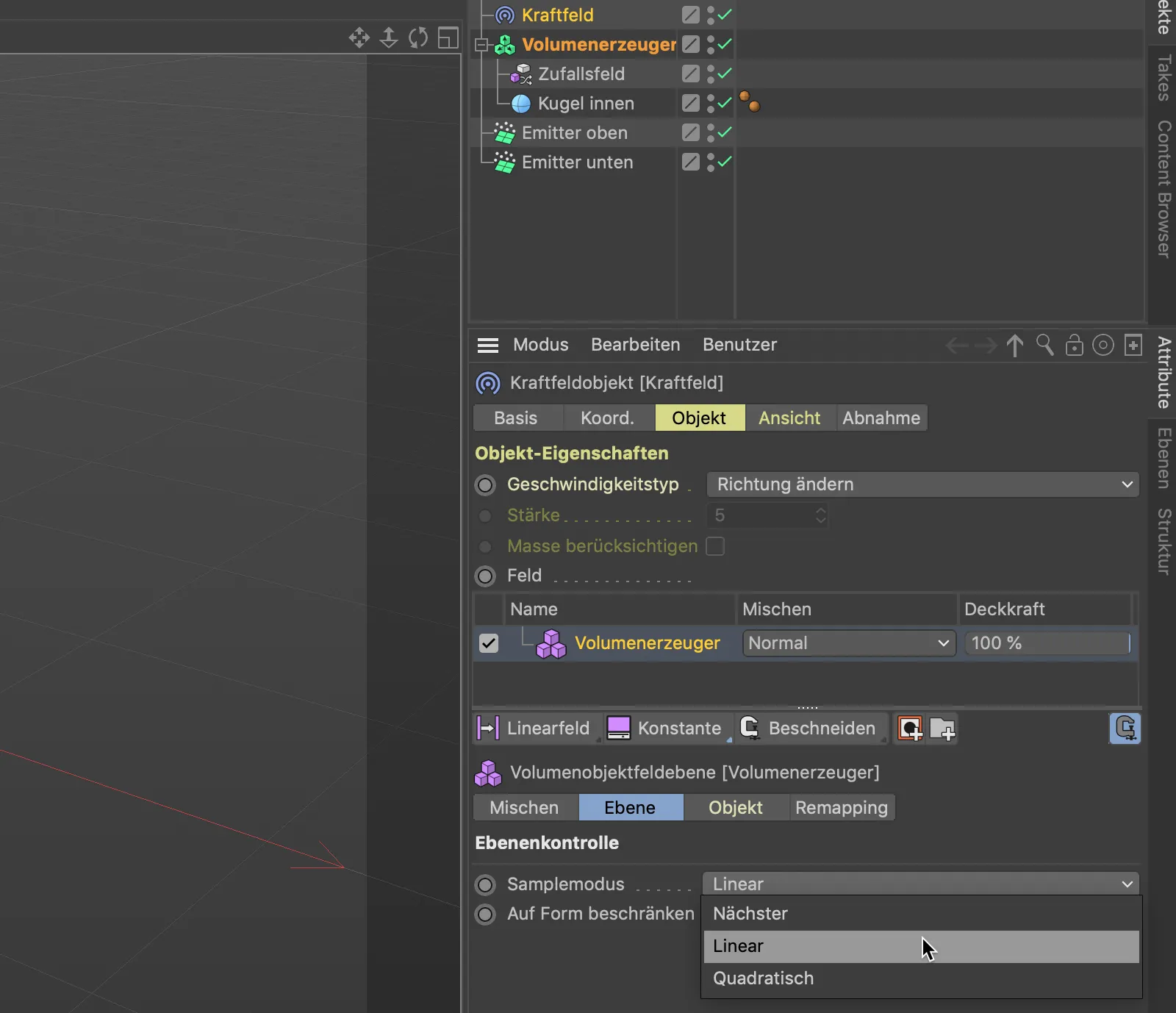
After this change, the particles deflected by the sphere move around much more freely. We immediately ensure that these particles also remain on the surface of the sphere.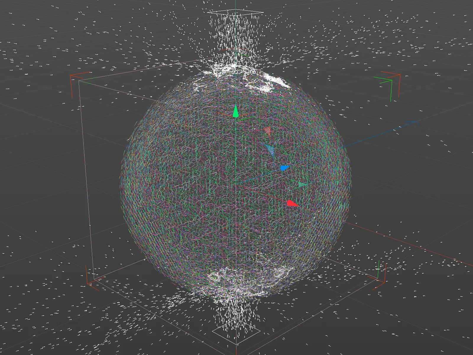
To ensure that the paths of the particles moving on the surface of the sphere are not too delicate, we increase the size of the underlying noise in the settings dialog of the random field. Of course, everyone is free to experiment a little further with the settings of the random field.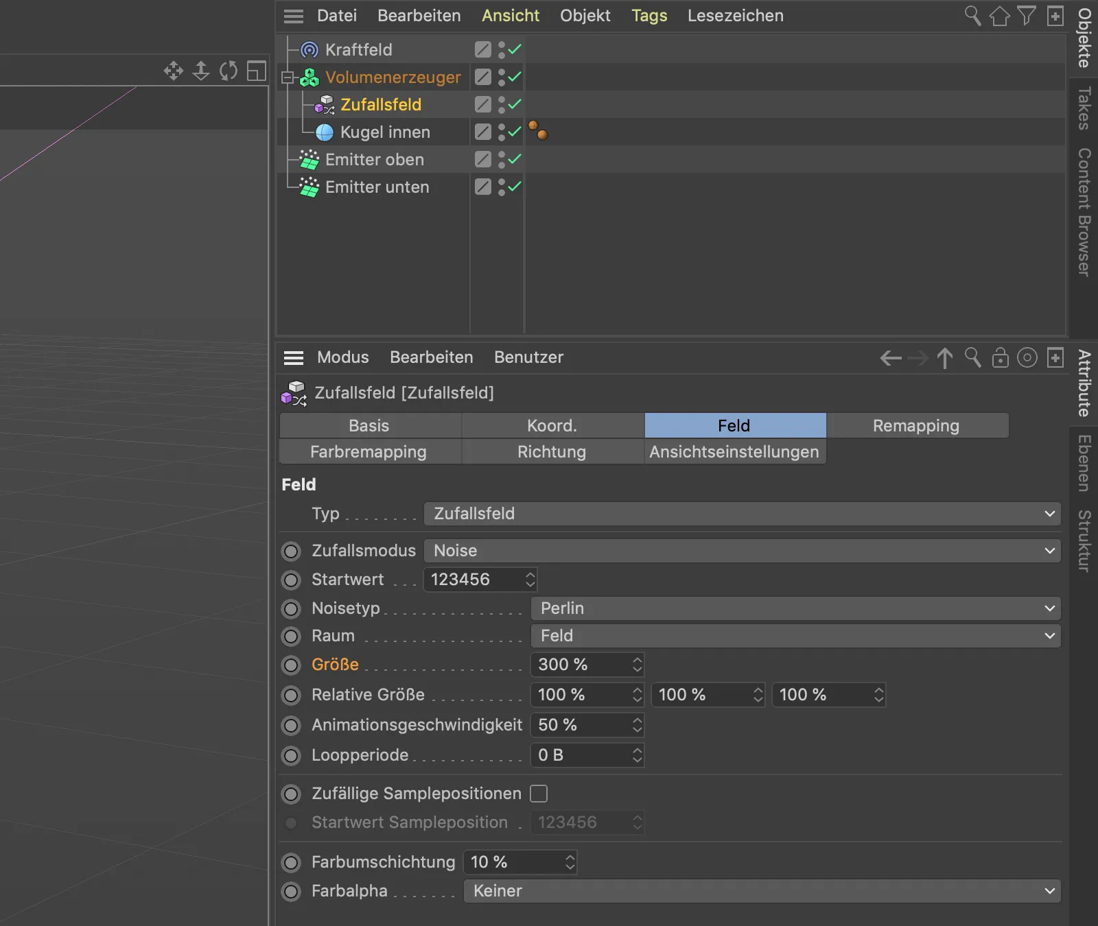
If we have selected the random field object, we can change the size parameter interactively in the 3D view using a separate gripper.
I decided on a size of 300 % so that the noise in the vectors is clearly visible.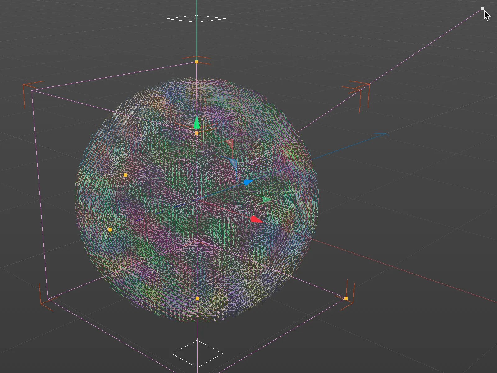
Structure of the second vector field
As the name of our sphere object "Inner sphere" suggests right from the start, there should also be a second vector field for an outer sphere in addition to the vector field just completed for the inner sphere. This second, slightly larger sphere should ensure that any reflected particles are sent back to the surface of the inner sphere.
To do this, we duplicate the sphere object in the Object Managerby holding down the Ctrl keywhile dragging it, leave it as a sub-object of the volume generator and add the suffix "outside" to it in order to be able to distinguish between the two spheres. We also give this outer sphere a 2 cm larger radius as a margin for the particles.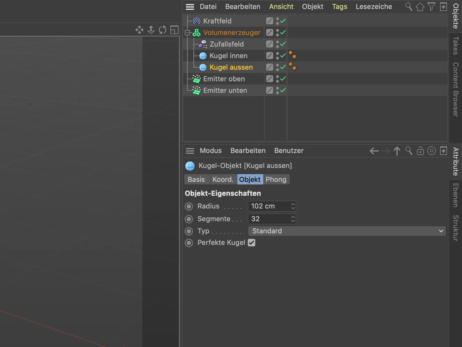
The volume generator has also generated the corresponding vector field from the second, outer sphere and added it to the existing objects.
In the list of objects in the settings dialog of the volume generator, the outer sphere is now at the top of the list and would be processed last. However, we want the outer sphere to be penetrated by the particles first and then no longer release the particles.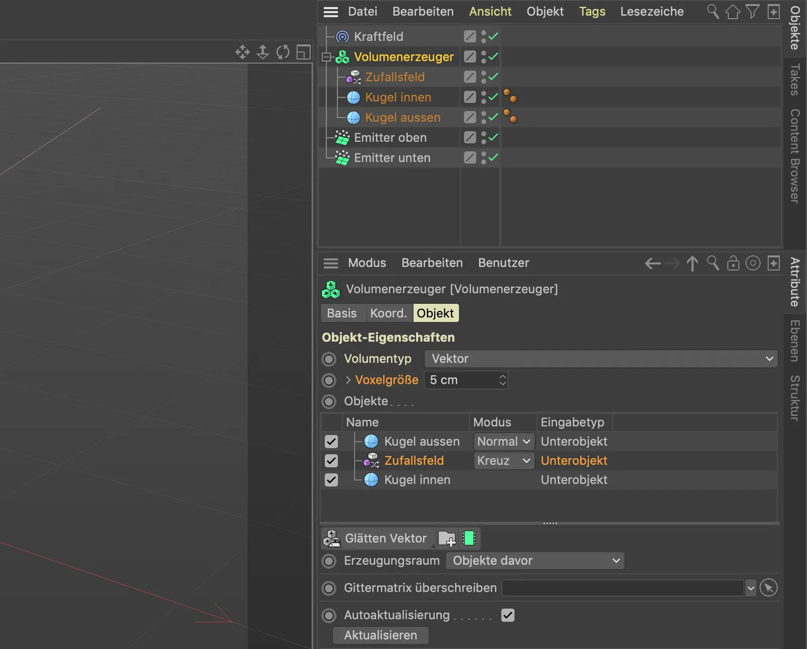
So let's bring some order to the object list. First, we move the "outer sphere" to the lowest position in the sequence. Because the random field affects the "inner sphere" below it, but should be processed directly after the "outer sphere", we simply create a folder into which we can move the random field and the inner sphere. To do this, we click on the folder buttonbelow the object list.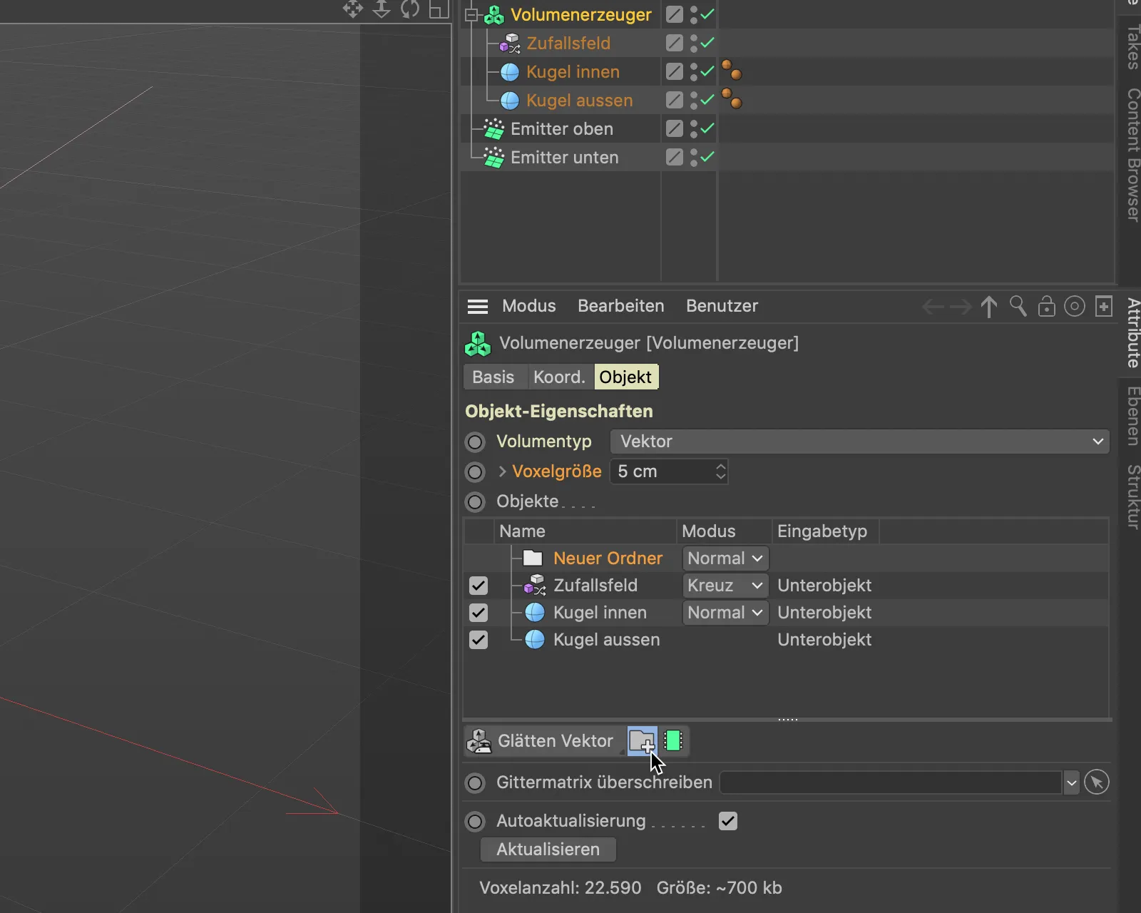
Now we drag and drop the random field and the inner sphere from the object listof the volume generator into this new folder.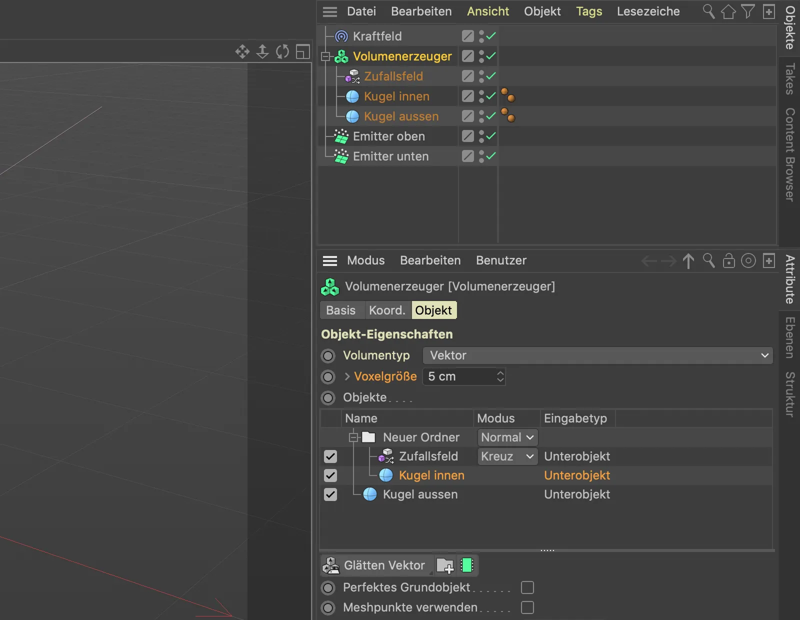
As the outer sphere, whose vectors are perpendicular to the surface of the sphere, is the first to act, any particles hitting it are still completely reflected at the moment. To invert the vector field of the outer sphere, we use a volume filter, some of which are also available for working with vectors. We find the volume filter menubelow the object listand select the Invert vector filter.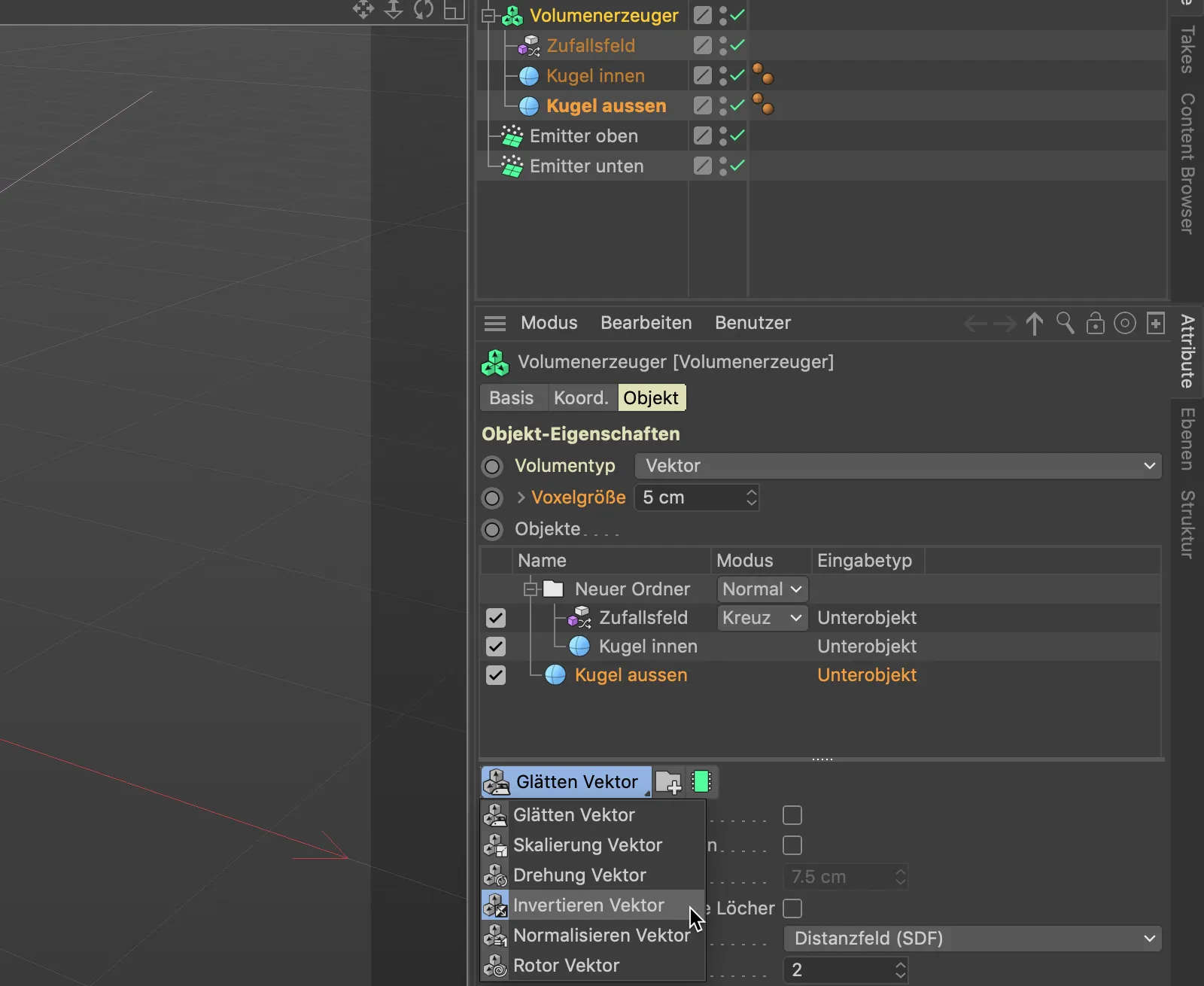
As we only want the volume filter to affect the vectors of the outer sphere, we drag and drop it directly above the "Outer sphere".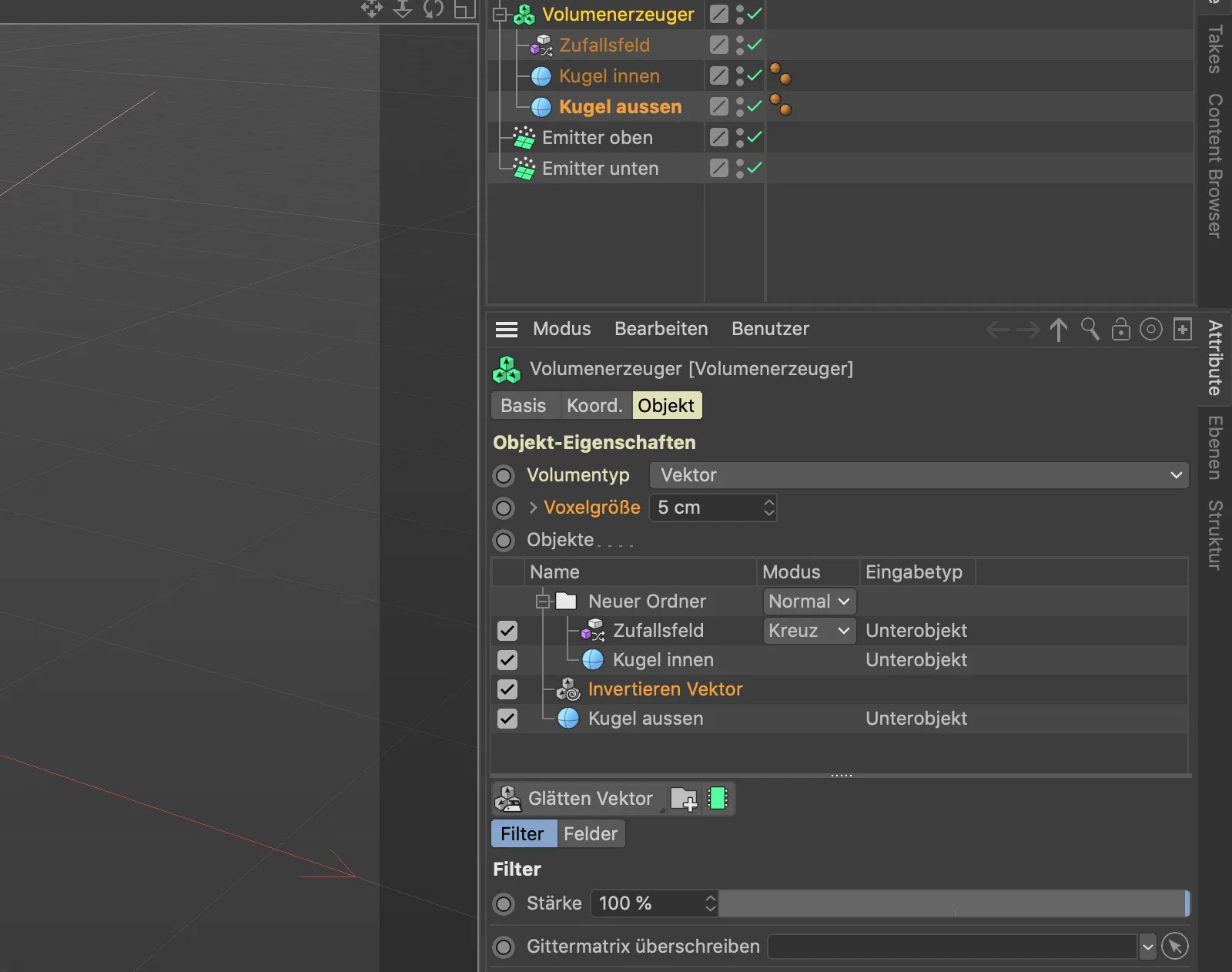
Now everything should work as desired. A click on the play button shows that all vector fields are set correctly. The particles hit the sphere and are distributed randomly over the surface.
We can add a little more life to the particle streams by animating the noise patternof the random field.
To do this, we call up the settings dialog of the random field and set an initial speed, in my example 50%.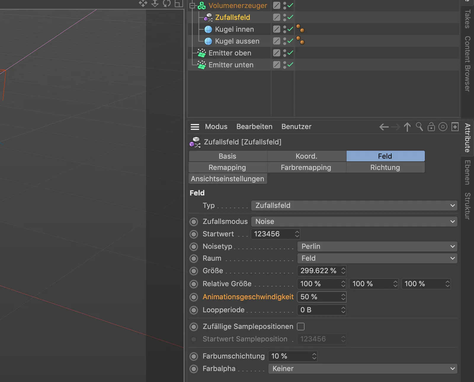
The particle streams now become shorter due to the animated noise pattern, they break apart in more places.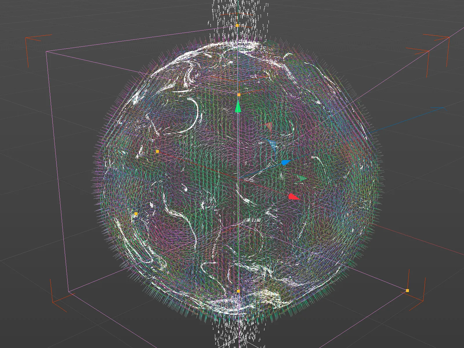
Converting the particles to spline paths
Of course, we can now send any - preferably small - object on its journey across the surface of the sphere as a particle. An alternative is to automatically trace the paths of the particles and convert them into spline paths. To do this, we need the tracer objectfrom the MoGraph menu.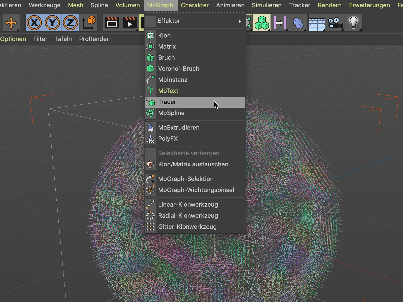
To convert the particle streams of both emitters into spline paths, we drag and drop the two emitter objectsvia the Object Managerinto the Tracer link field in the settings dialog of the tracer object.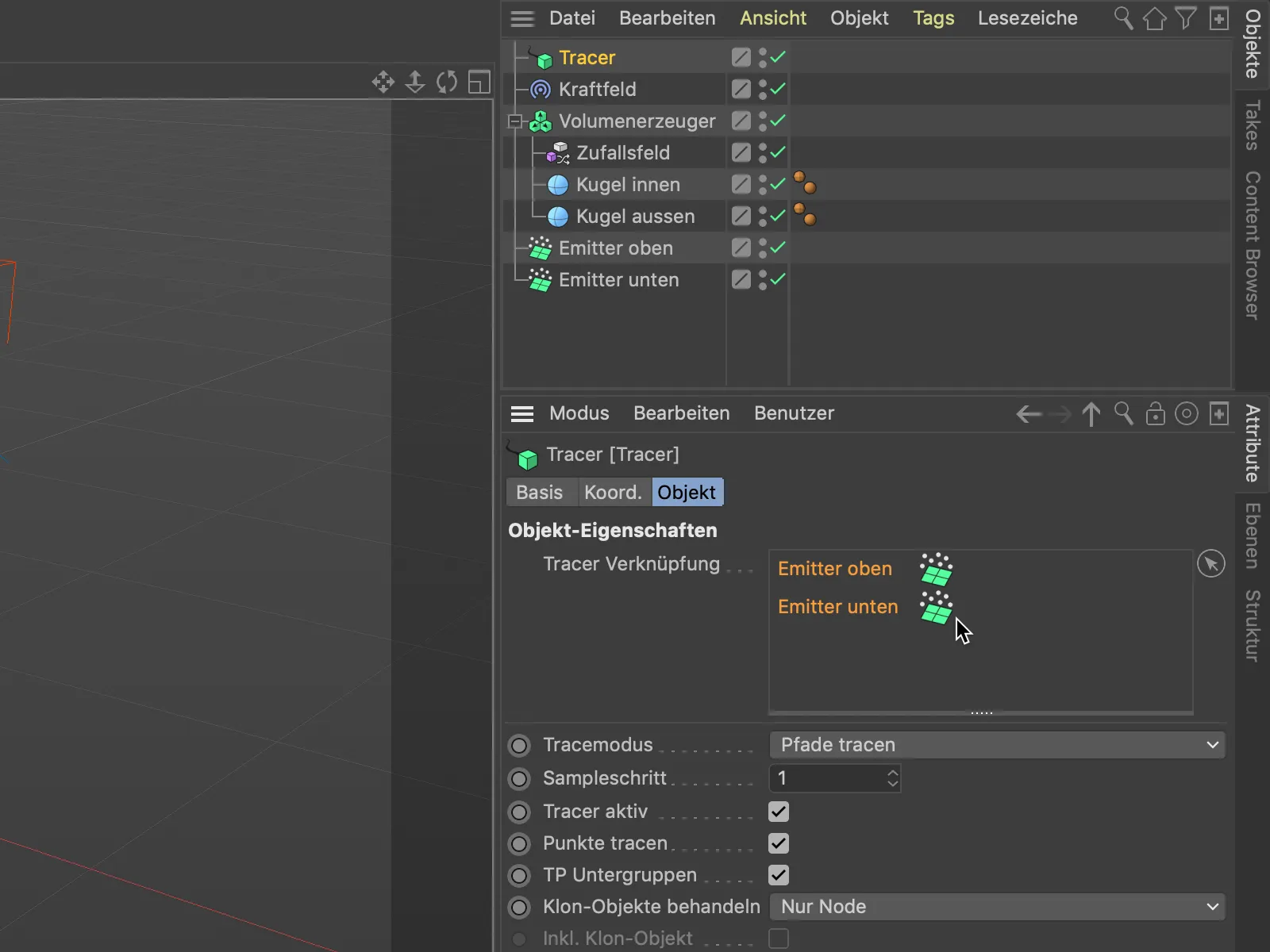
Because the emitters emit quite a lot of particles over time, we limit the length of the spline paths generated by the tracer. In the settings dialog of the tracer object, we select the end as the limit ...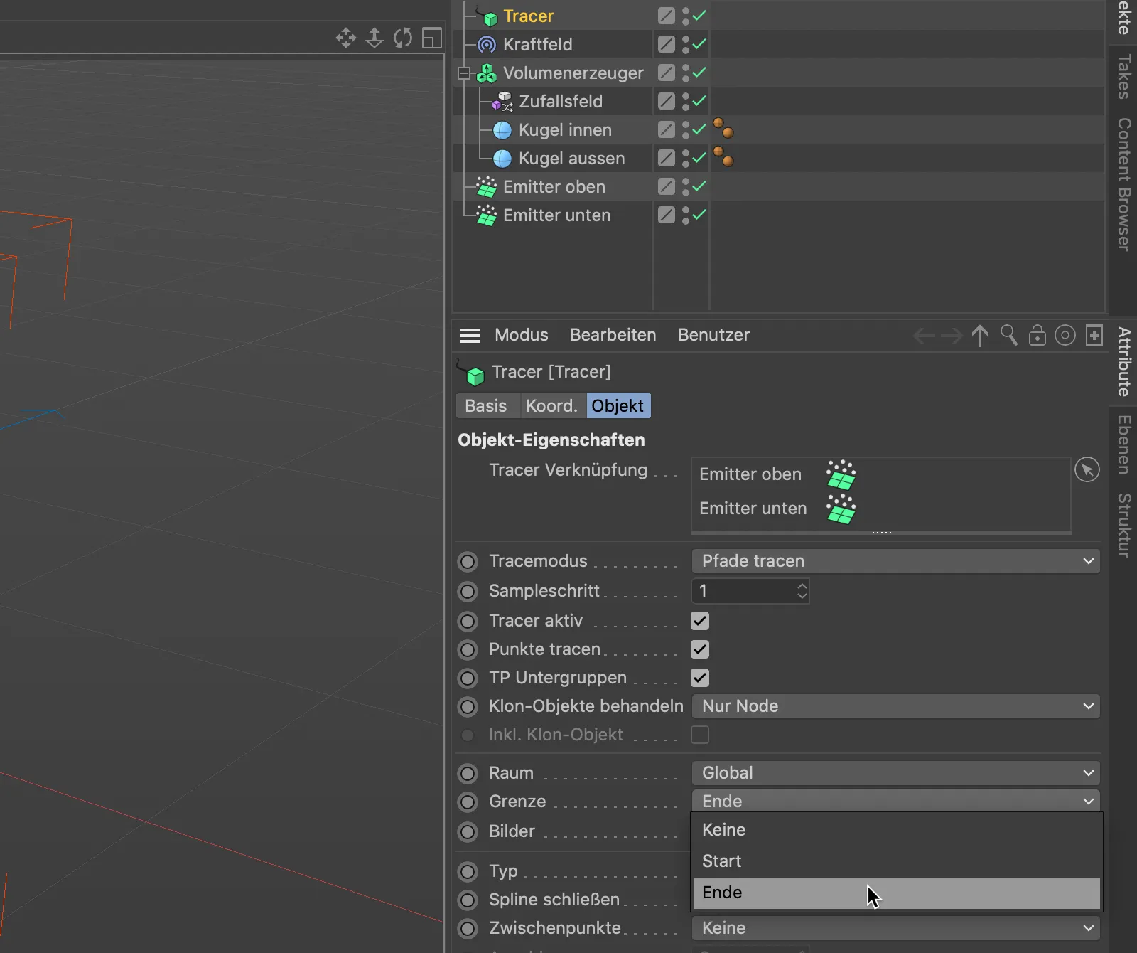
... and use the Images parameter to define the length of the spline paths. I have decided on a length of 100 images. Lower values result in correspondingly shorter spline paths.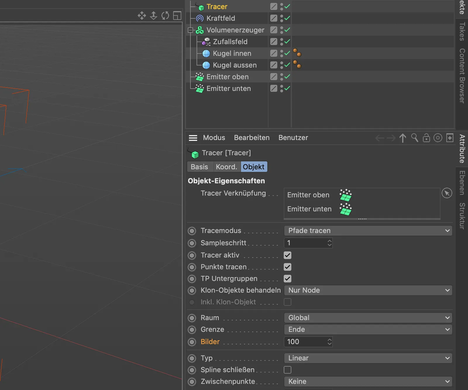
After clicking on the play button, we can now observe how the spline paths generated by the tracer move animatedly across the surface of the sphere.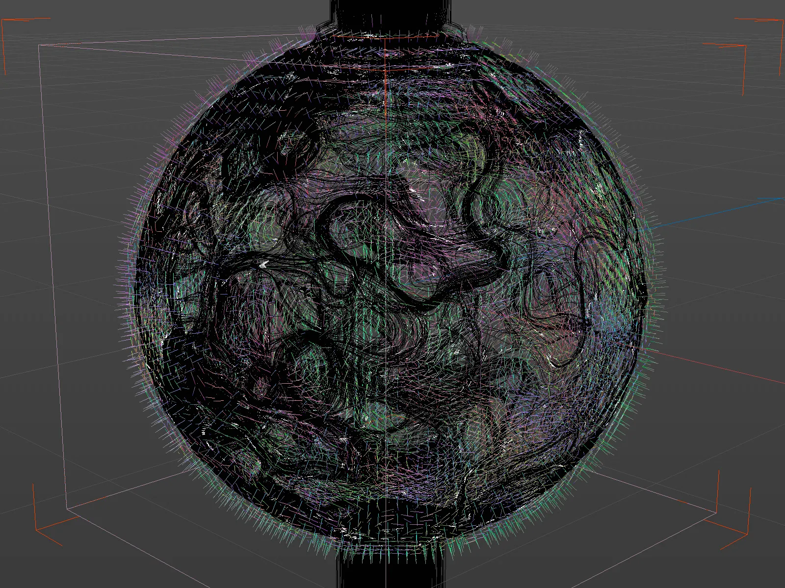
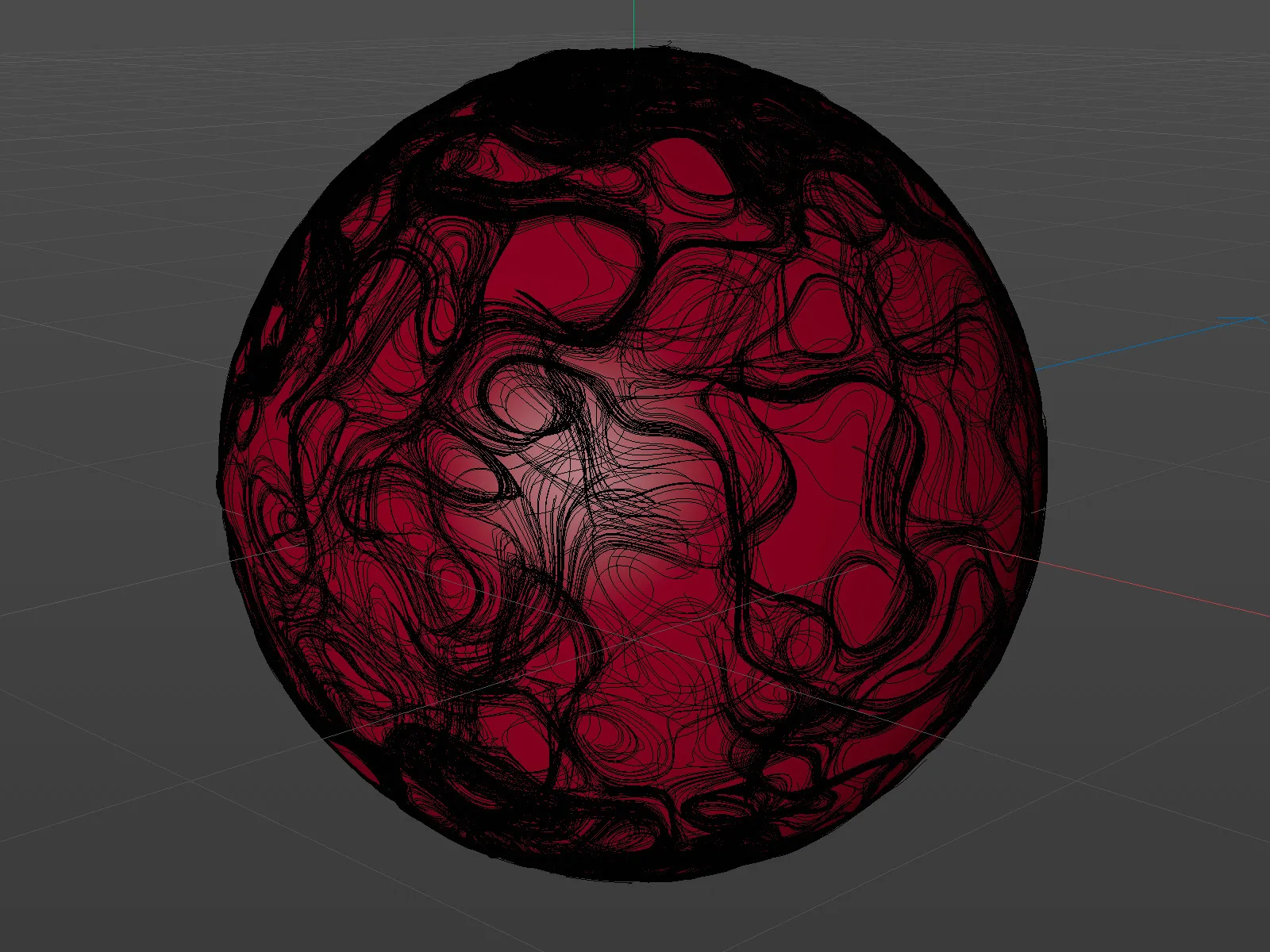
For the lead image of this tutorial, I have created a duplicate of the sphere object and covered it with a red material. With the exception of the tracer object, we can deactivate the visibility of all other objects in the Object Manager.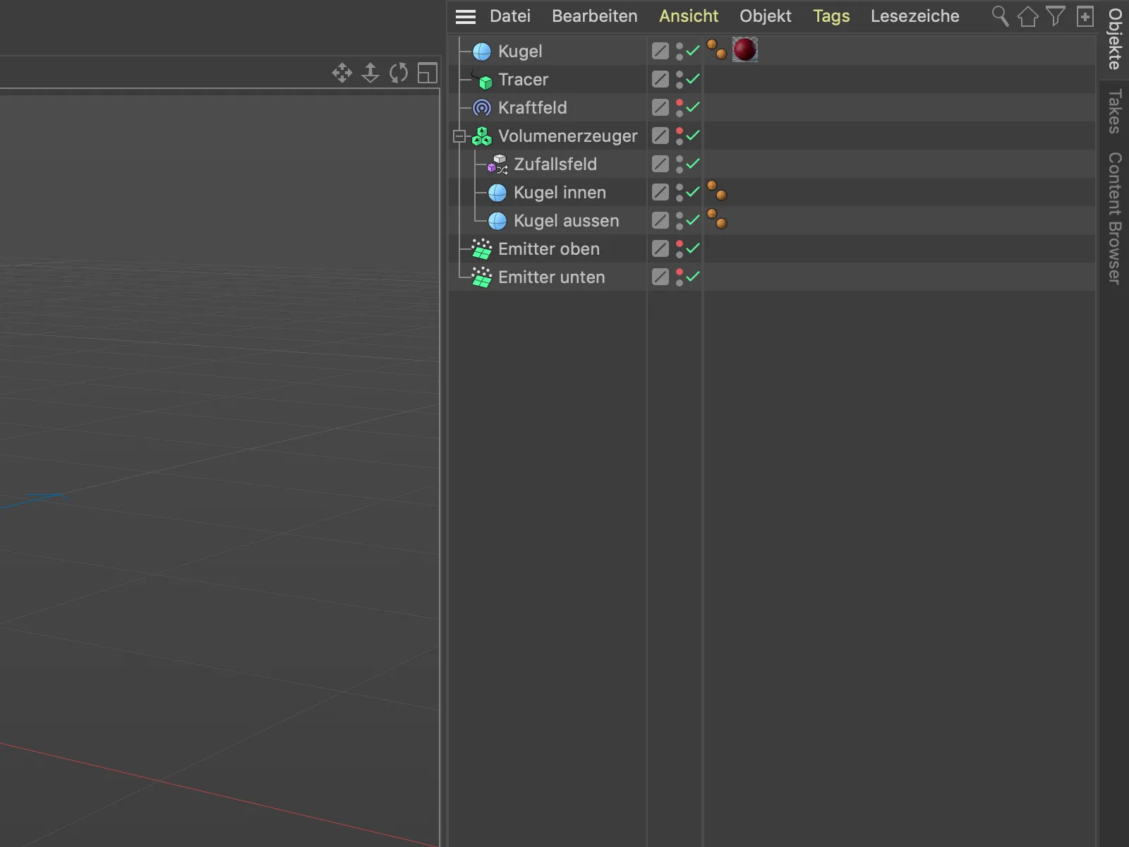
To create three-dimensional objects from the spline paths generated by the tracer object, you can subordinate the tracer objectto a sweep objecttogether with a circle object, for example. In this case, however, pay attention to the number of particles and their lifetime, as otherwise the computer will very quickly come to its knees ...