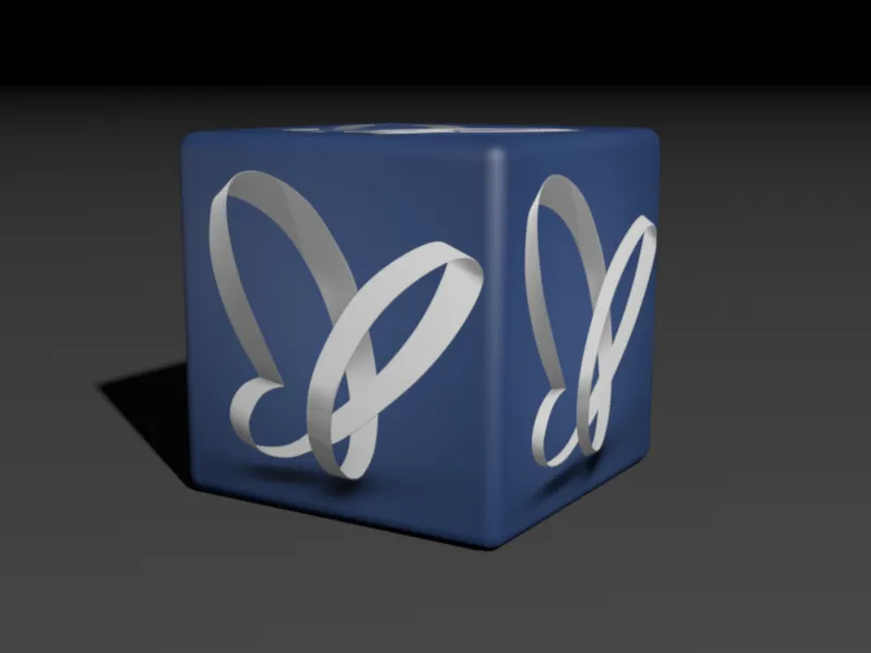
We will take a look at the new functions of the Voronoi break objectusing two short projects. As usual, you can find the source and final files in the working material for this tutorial. Under these two links, Animation_1 and Animation_2, you can view the two rendered animations for the two small projects.
The source file "PSD_C4D_R19_VoronoiBruch_Detail+Konnektoren_Start.c4d" contains an illuminated scene including a ground object on which a blue block with the familiar PSD butterfly can be seen.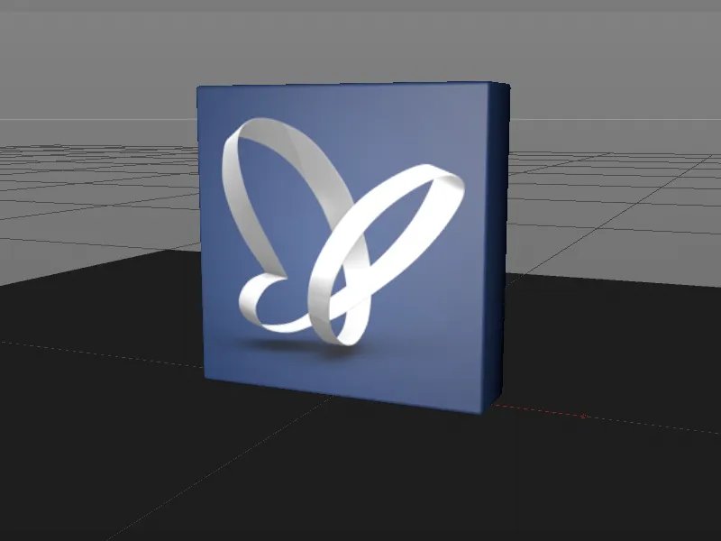
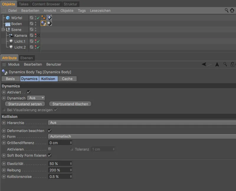
So that we can concentrate fully on working with the Voronoi fracture object, the scene contains a camera intended for rendering. The floor already has a Dynamics Body tagas a collision object with a high friction value so that the fragments breaking out of the blue block come to a quick stop.
Creating the fragments with the Voronoi break object
In order for the blue block to break, we have to divide it into fragments using the Voronoi breakobject. To do this, we select the parametric cube of the blue block in the Object Managerand create a Voronoi break objectvia the MoGraph menu while holding down the Alt key. By adding the Alt key, the cube is immediately subordinated to the Voronoi break object.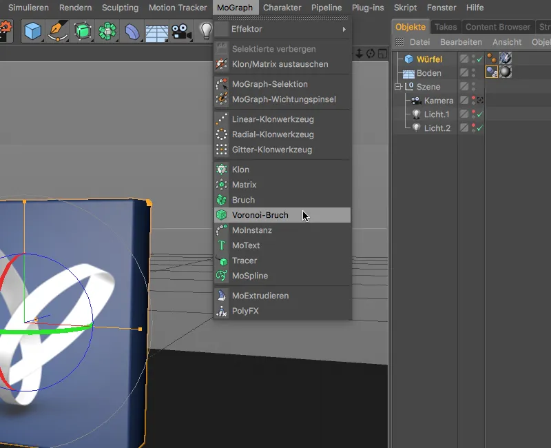
After this step, the block already has the first color-coded fragments, which of course do not yet meet our requirements. Release 19 offers a simple option for modifying the fragment cells on the object pageof the settings dialog under Scale cells. In this way, authentic fragments can be created very quickly for fibrous materials such as wood. As our block is to be made of ceramic or porcelain, we will leave the default settings here.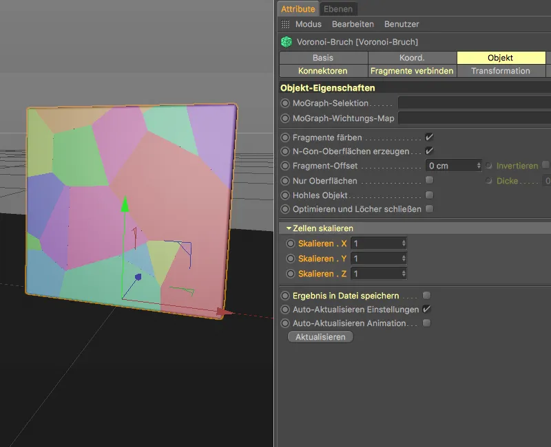
On the Sources pageof the settings dialog, we find the distribution source of the currently applied fragments. With a few changes, this point generator is already sufficient for our block fragments. We set the distribution type to Exponential and reduce the standard deviation to 0.11 so that the fragments are initially concentrated and then become larger.
As the block is to fall from top to bottom, we place the effect of the fragment distribution exclusively in the positive direction on the Y axis. A number of points of 300 ensures sufficient fragments, while the specified random starting value promises a rather nice fragment arrangement.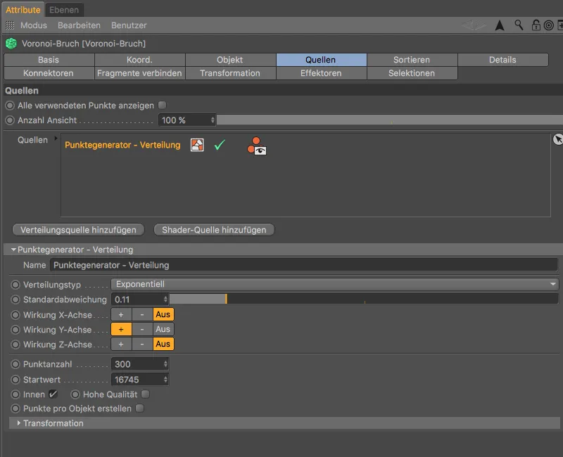
After these preparations, you can already get a pretty good idea of how the block will break. The smallest fragments are at the bottom end, as the block hits directly at these points.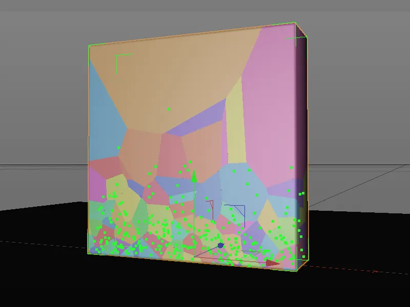
Dynamic properties for the block
Before we continue working on the Voronoi fracture object, we test the current state of fragmentation by assigning a Rigid Body Dynamics tag to the Voronoi fracture objectvia the context menu using the right mouse button or via the Tags>Simulation Tags menu in the Object Manager.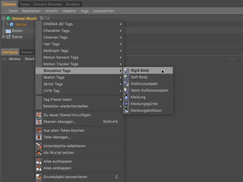
In the settings dialog of the Rigid Body Dynamics tag, we must pay particular attention to a new option added with Release 19 so that the fragments of the block do not separate prematurely due to the fragment deformation that will soon follow. So make sure that the option Observe deformation is not activated.
Take this opportunity to increase the friction to 80% and reduce the elasticity to 20% so that the fragments do not bounce back too high and soon come to a stop on the floor.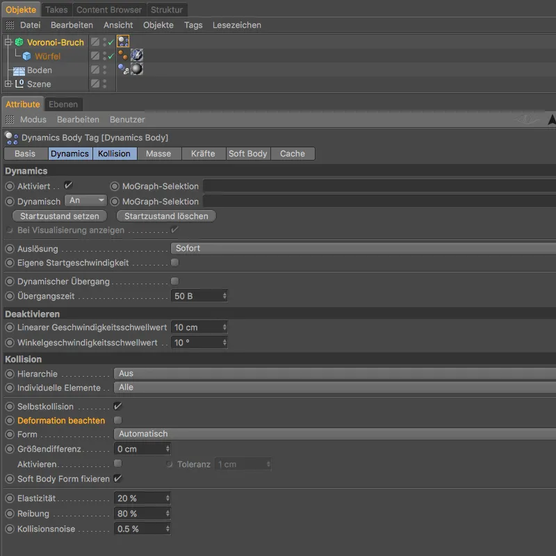
Now we just need to raise the blue block a good distance so that the height of the fall causes the fragments to shatter. For our first test, we change the Y-coordinateof the Voronoi fracture objectto 750 cm or more using the Attribute Manager.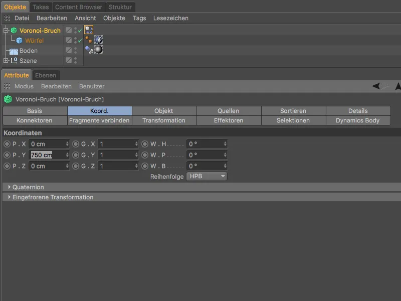
After clicking on the play button, the blue block falls down onto the floor object and shatters completely into the fragments we defined previously. Up to this point, the Voronoi break objectbehaves as known from the previous version.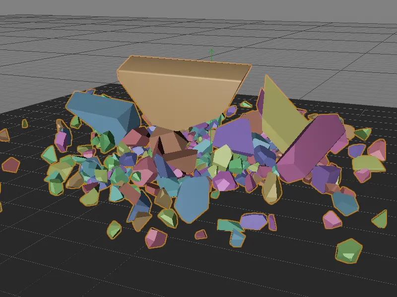
If we zoom in a little closer to the fragments, we quickly notice that the fracture surfaces - each one on its own - are absolutely smooth.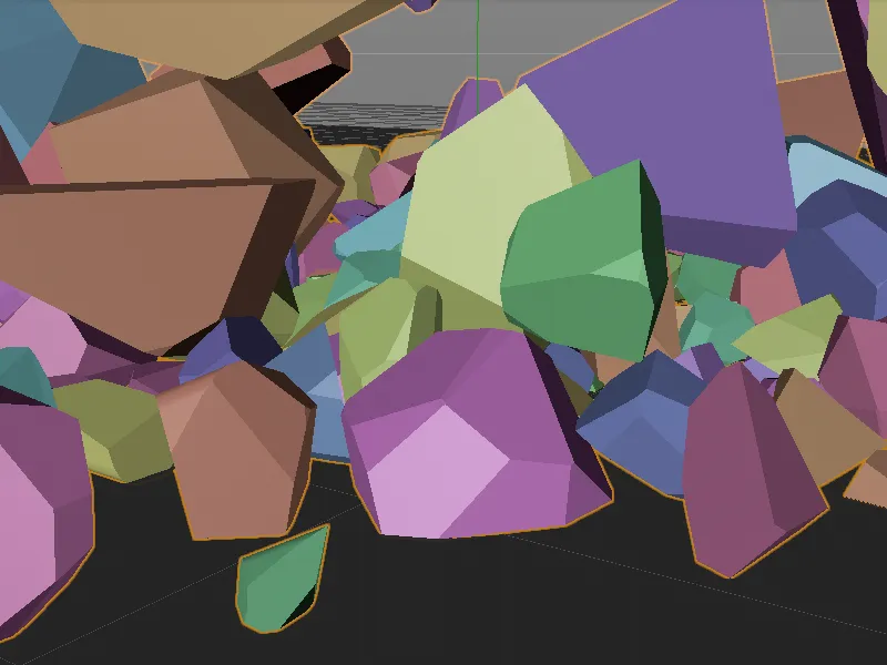
More realistic fracture surfaces through details
This is where the first major innovation of the Voronoi fracture objectcomes in. On the Details pageof the settings dialog, we find the option to activate these very details. Noise is used to transform the unwanted smooth fracture surfaces into realistically shaped fractures.
In the Noise settings section, we find parameters that are strongly reminiscent of the familiar noise shaders. With the depth intensity graph, it is even possible to control the effect of the noise deformation along the fracture depth.
First, let's switch on the generation of details at the top of the basic settings using the Enable details option. We use the maximum edge length to regulate the subdivision of the deformation; the default value of 10 cm is sufficient here. As we do not want to deform the surface itself, we leave the Deform surface option deactivated. We can also leave all other parameters at their default values.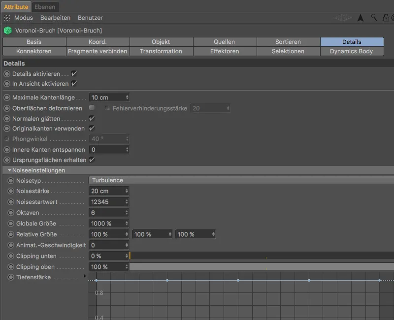
If we now take a closer look at the fragments, we can clearly see the deformation of the fracture surfaces caused by the details.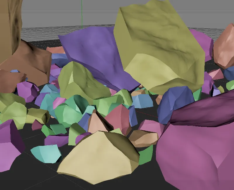
So that these fracture surfaces can be assigned a different material in addition to the deformation, we switch to the Selections pageand activate the Inner surfaces option. This creates a polygon selection of the inner surfaces for the block and assigns it to the Voronoi fracture objectusing a selection tag.
New in Release 19 is the option to create vertex maps for the inner and outer surfaces as well as the edges in the same way.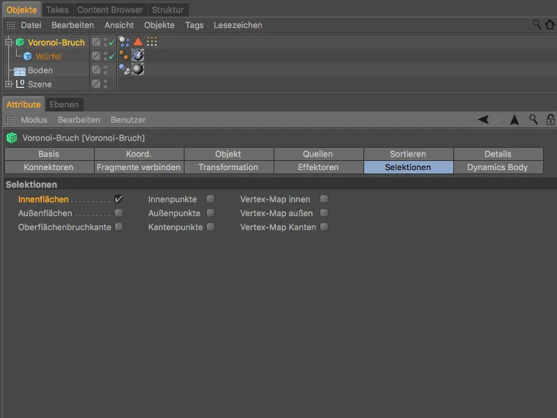
In the Material Manager, you will find a material called Inside that you can use for texturing the fracture surfaces. We drag it from the Material Manageronto the cube object of the block in the Object Managerto assign it to the block.
In the settings dialog of the resulting texture tag, we find the Selection field on the tag page, into which we drag the polygon selection tagfrom the Object Managerfor the inner surfaces.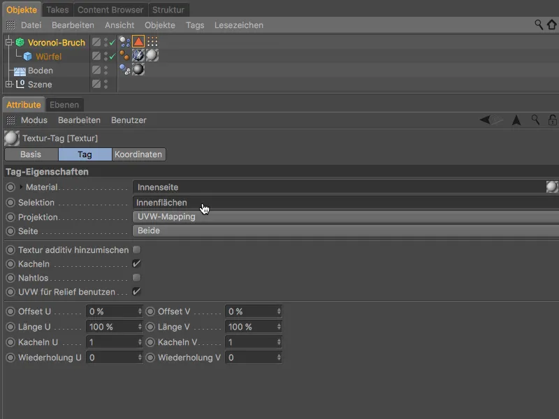
As the test rendering shows, the fracture surfaces of the block are not only deformed, but also have a slight grain for an even more realistic appearance.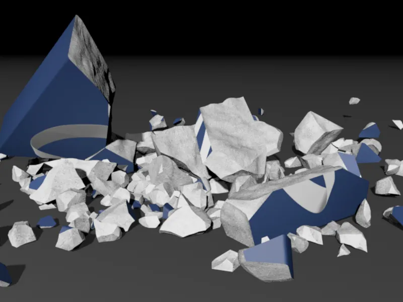
Correctors to control the breaking strength
The next major innovation of the Voronoi fracture objectconcerns the fracture resistance of the fragments. The object falling to the ground always shatters into its fragments, regardless of the actual force applied.
In order to provide a control option here, the Voronoi breakage objecthas a connector pagewith Release 19, which we can use to clamp connectors between the fragments. To do this, we simply click on the Create fixed connector button.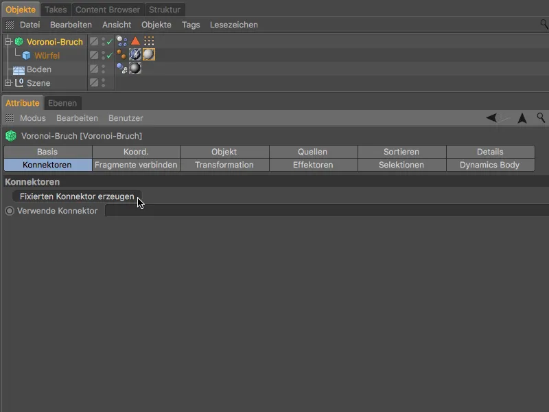
Before we continue with the setting of the connectors, we first test the animation by clicking on the play button. Only the fragments that are affected by the force will actually break off.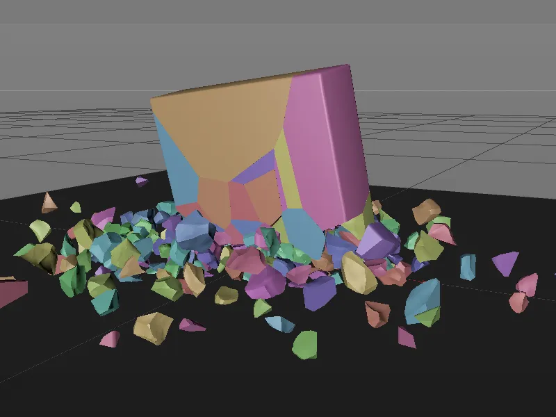
When we clicked on the Create fixed connector button, a connector objectfrom Dynamics was assigned to our Voronoi break object, which fixes all fragments with the force specified for it. We can use the settings dialog of the connector to control this breaking force or the breaking torque, in our case with a value of 80000 for both parameters.
The fixed connector type is installed by default, but you can of course also use other connector types, for example to create bending fragments.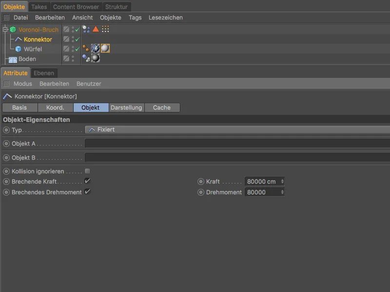
With this setting, a little more of the blue block remains intact - so the butterfly logo remains clearly visible.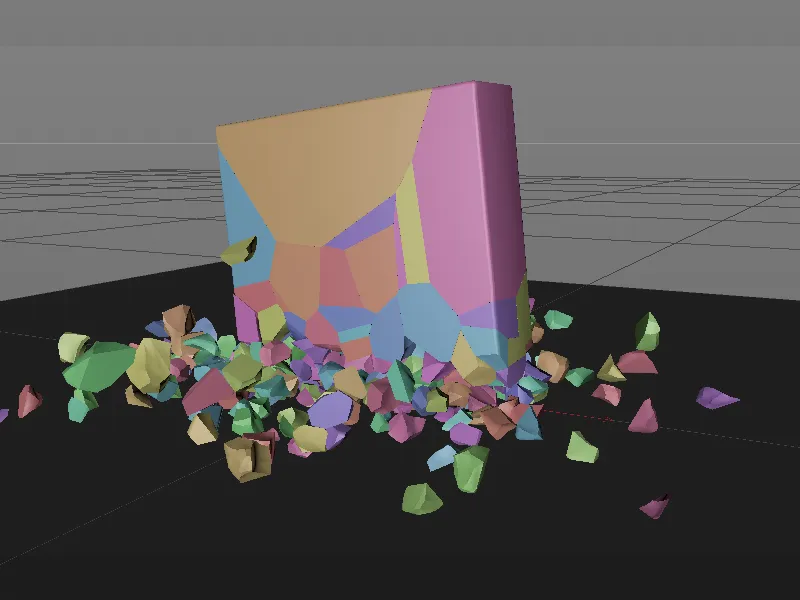
As desired, the block no longer breaks apart completely; its fragments are held together by the connectors until the specified force is applied.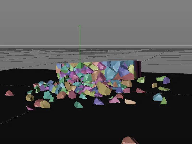
Finalizing the first animation
To make the fall of the blue block even more credible, we set it to a sufficient initial height using the coordinate sideof the Voronoi fracture objectand tilt it slightly to the side and very slightly backwards.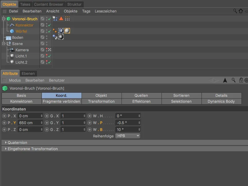
After this step, the first animation of this tutorial is complete.
Release 19 has added even more new functions to the Voronoi break object, which we will now look at in a second part.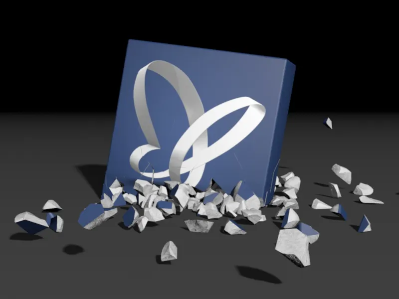
Assembling with the Voronoi break object
For this part of the tutorial, the source file with the name "PSD_C4D_R19_VoronoiBruch_Fragments+Sort_Start.c4d" again contains an illuminated scene including a ground object, on which a blue cube with a PSD butterfly on each side can be seen.
So that we can concentrate on the next innovations, the cube is already evenly fragmented into 300 pieces by a Voronoi break object.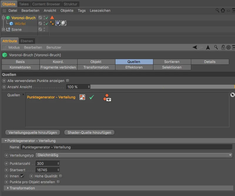
In this second part of the tutorial, we will not break the cube but assemble it from its fragments.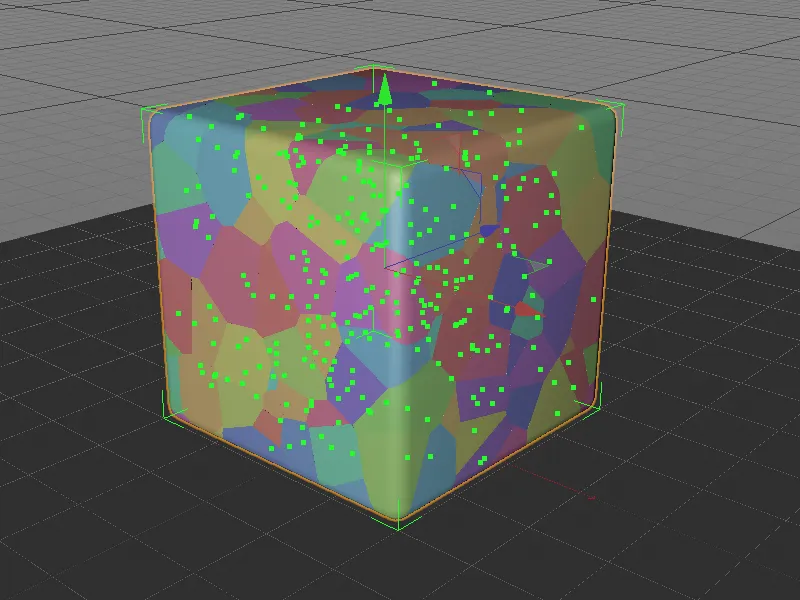
Joining fragments
Once again, new functions of the Voronoi fracture object will help us, because we first want to make the 300 fragments a little more manageable. To combine the existing fragments a little, we switch to the Combine fragments pageof the settings dialog and activate the Combine fragments option.
To connect the numerous fragments into several clumps, we set the connection type to clump and enter the number of clumps as 30.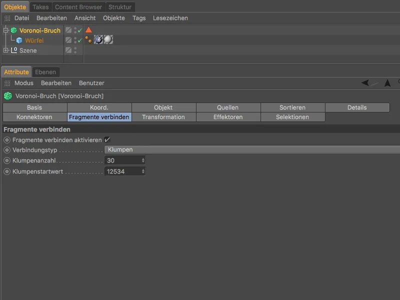
In the editor view, the clumping of the fragments can already be seen in the changed color distribution. So that we can also see the inner surfaces of the combined fragments, we select the Voronoi break objectand assign it a displace effector via the MoGraph>Effector menu.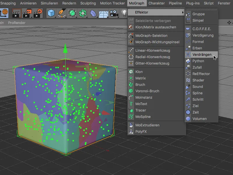
The displace effectorpushes the lumps apart for us so that we can better recognize the connected fragments as well as the inner surfaces. The cube should now be assembled piece by piece from these 30 lumps. As we will no longer need the displace effect, you can select and delete it via the object manager.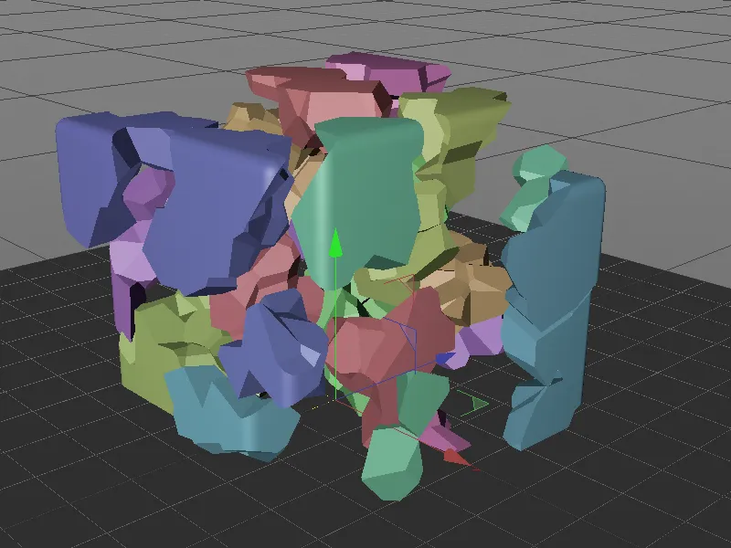
Assembling the cube with the step effector
For step-by-step processing such as assembling the cube, the step effectoris of course predestined. We select the Voronoi fraction objectagain and assign the step effectorto it via the MoGraph>Effector menu.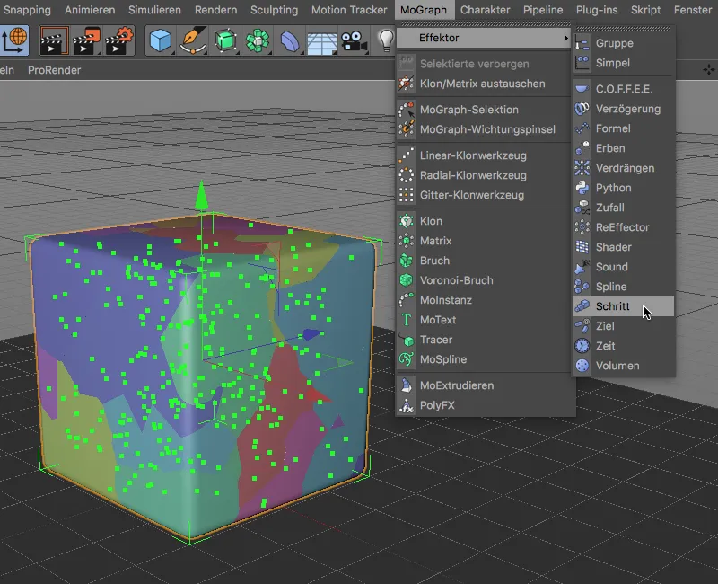
In the settings dialog of the step effector, we control the assembly of the cube via the Strength parameter on the effector page.
First, however, we set up the step effector. So that the effector does not scale the lumps, but moves them upwards in the Y direction, we deactivate the Scaling option on the parameter pageand activate the Position option with a Y valueof 20000 cm instead. To make the offset linear, right-click in the spline graph on the effector pageand select the Reset option.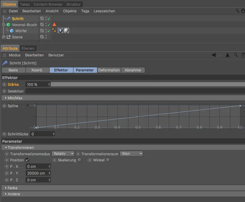
We can now use the value of the Strength parameter in the step effectorto control the step-by-step offset of the lumps. What we notice immediately is that the clumps use their own sequence, which means that some clumps overlap.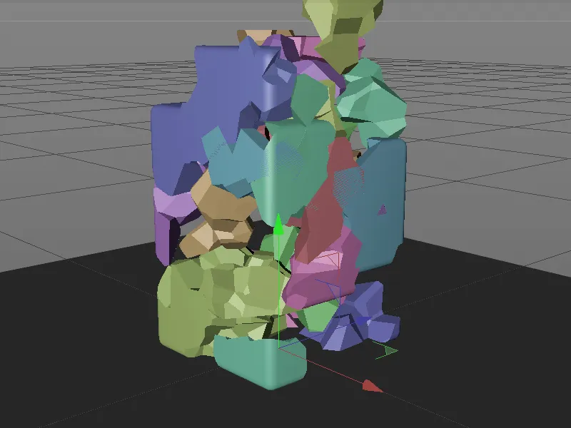
Sorting the fragments
To solve this problem, we use the latest innovation of the Voronoi Fracture object, the Sort pageof the settings dialog. Here we can specify a sorting of the fragments after activating the Sort result option.
As the fragments should be arranged in the Y direction, we select the Y axisfor the sorting direction. To ensure that the assembly takes place from bottom to top, we also reverse the sorting using the Invert sorting option.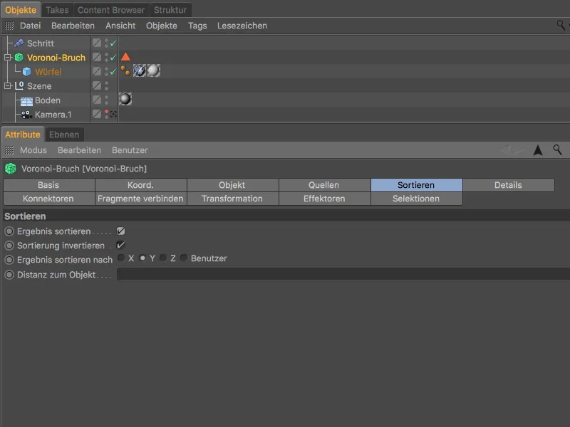
If we now test the step-by-step assembly again using the step effector, the clumps fit together much better.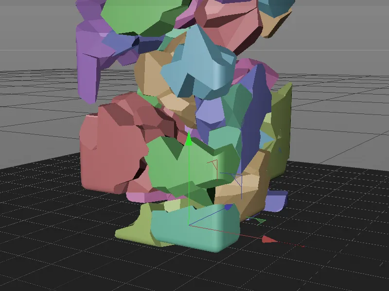
The sorting ensures that the assembly takes place in a sensible order and there are also far fewer overlaps.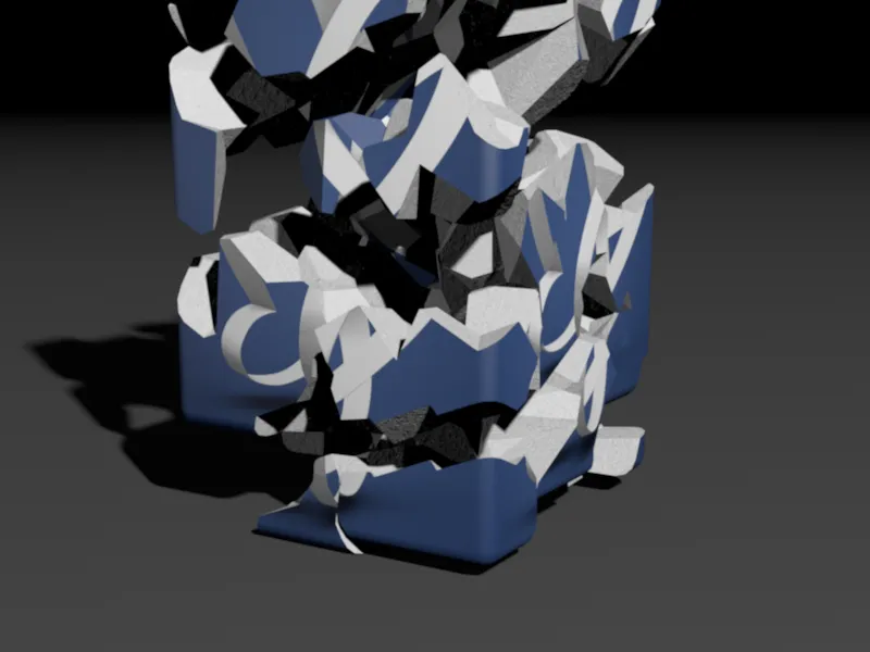
As soon as the strength valueof the step effectoris set to 0, the fragments or clumps of the cube are no longer visible.