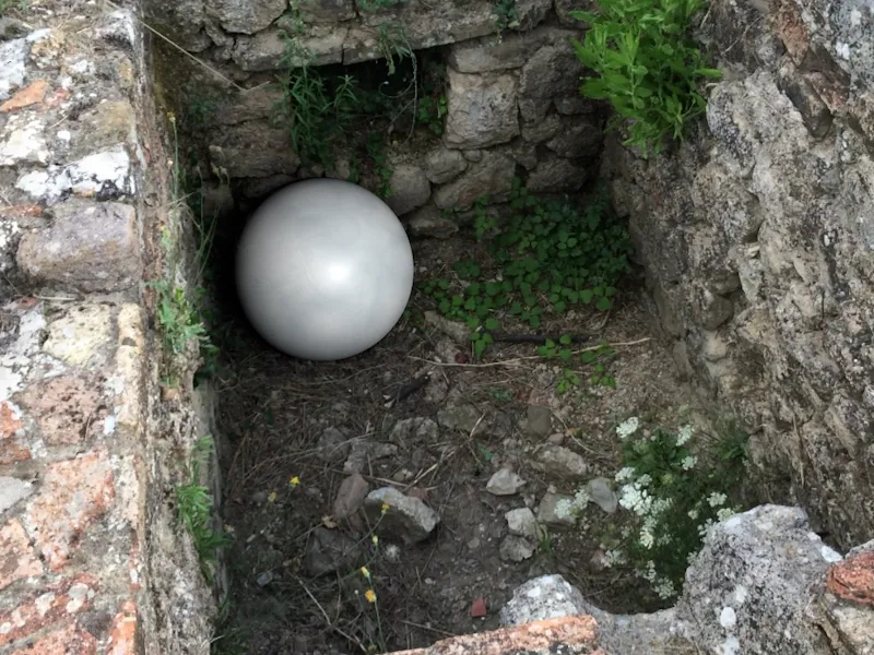
For this tutorial, I deliberately used very ordinary footage taken with a smartphone in order to encounter everyday problems. For example, the angle of the left wall is very steep and some plants are moving. If you would like to follow the tutorial directly, you can find the 2D movie "Mauern.mov" in the working material.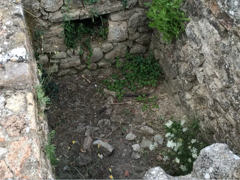
2D tracking of the footage material
As usual, we start the motion tracking workflow by tracking the 2D film. To do this, we get a motion tracker objectfrom the Motion Tracker menu into a new, empty Cinema 4D scene.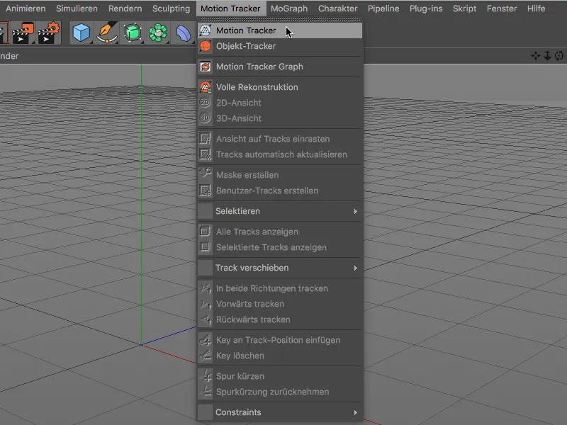
To enable the motion tracker to analyze the film, we open the settings dialog of the motion tracker objectin the Attribute Manageron the footage page. Click on the Load button in the footage line to open the Opendialog.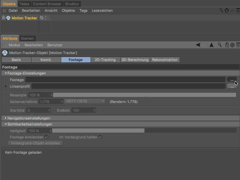
There you select the supplied 2D film as footage and load it into the motion tracker objectusing the Open button.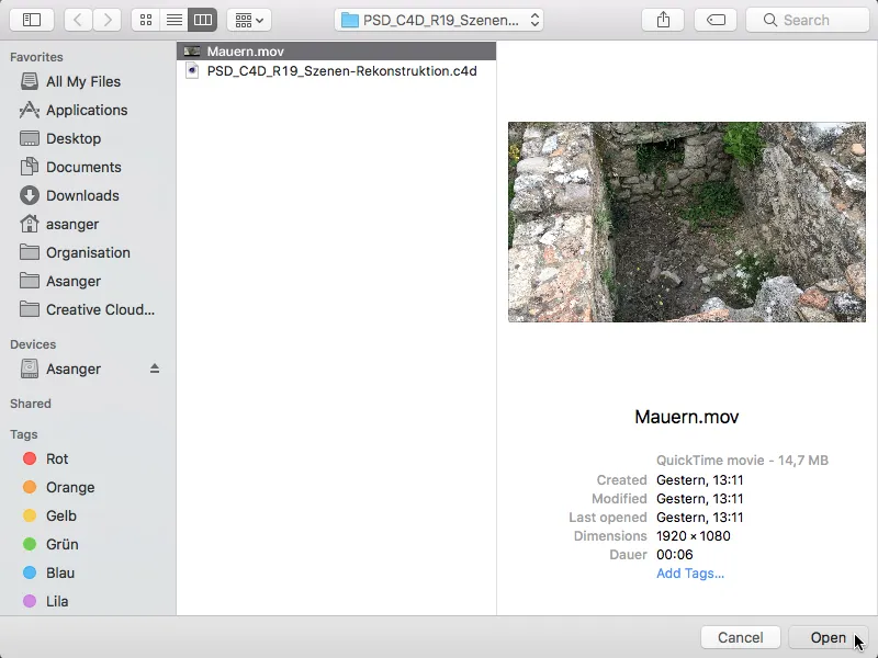
The resample value for analyzing the footage only refers to the upcoming tracking process for the camera reconstruction. Cinema 4D generally uses the best possible quality of the film for the subsequent scene reconstruction. However, even for camera reconstruction, a high value (apart from the slightly longer computing time) can do no harm.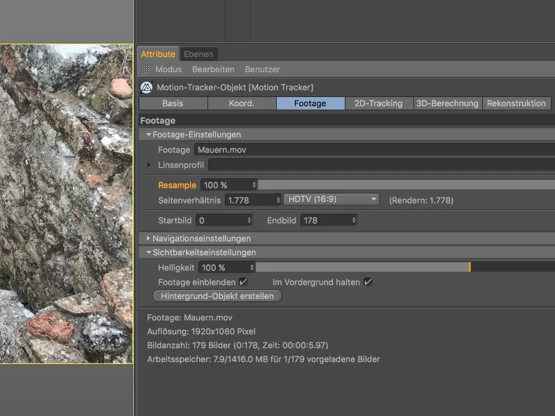
For 2D tracking, we switch to the page of the same name in the Motion Tracker settings dialog. We limit ourselves to automatic tracking, as we do not need any special tracking points for the subsequent construction. To ensure that sufficient tracking information is available, we set the number of tracks to 2000, with a minimum distance of 25.
After clicking on the Create auto-tracks button ...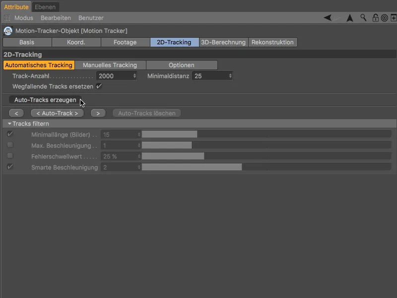
... we find the desired high number of tracking points very evenly distributed in our footage material.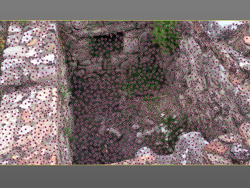
To make the motion tracker a little more tolerant of fast camera movements, we switch briefly to the Options pagebefore tracking and activate the Extrapolate search position option.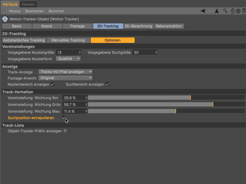
Now we can start 2D tracking on the Automatic tracking page by clicking the < Auto track > button.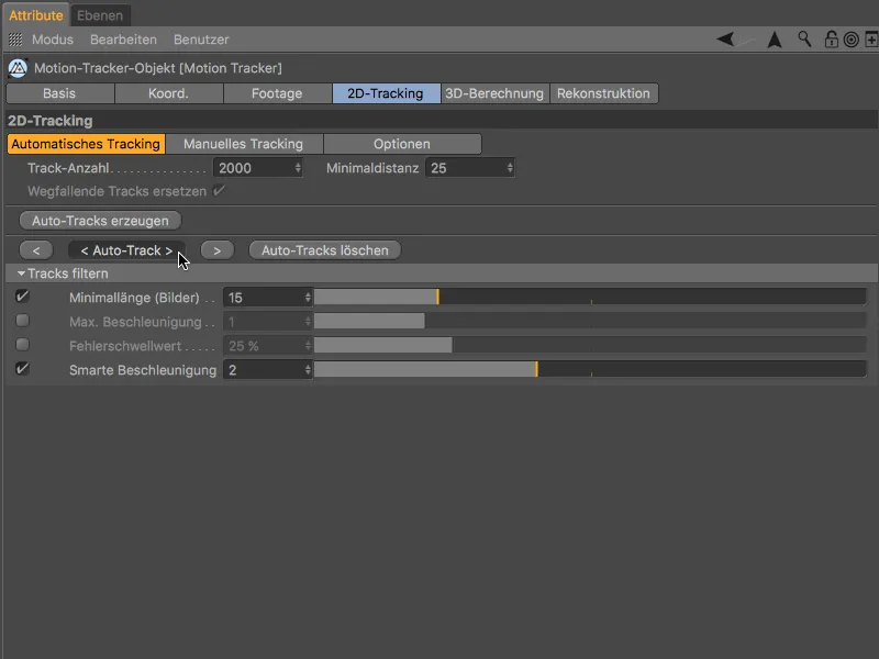
After the motion tracker has finished its work, we can test the tracked 2D film by clicking on the play button to check whether enough tracking points are retained over the entire course of the film.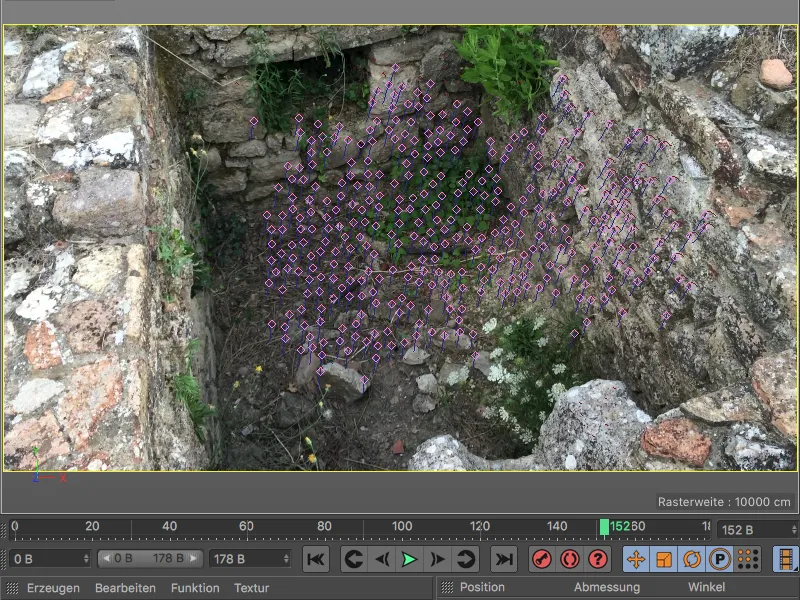
3D reconstruction of the camera
In the next step, we will reconstruct the camera information from this track information. To do this, we switch to the next page in the Motion Tracker settings dialog, 3D calculation. We can leave the default values for the full 3D reconstruction as the motion tracker should determine the focal length itself.
After clicking on the 3D reconstruction button, the 3D calculation of the camera information takes place.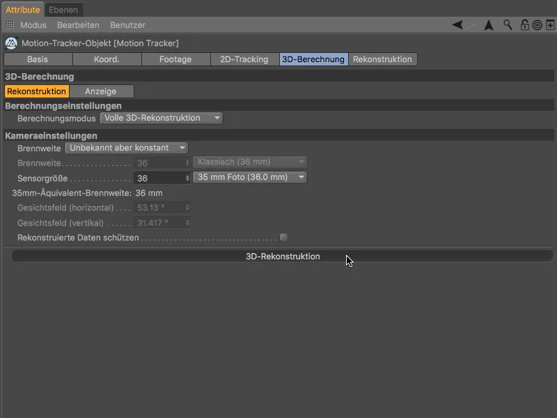
The result of the 3D calculation shows - as you would expect - most of the green features in the clearly visible, non-moving areas, while the moving plants and the steep left wall remain the problem areas marked with red features due to the relatively fast movements of the camera.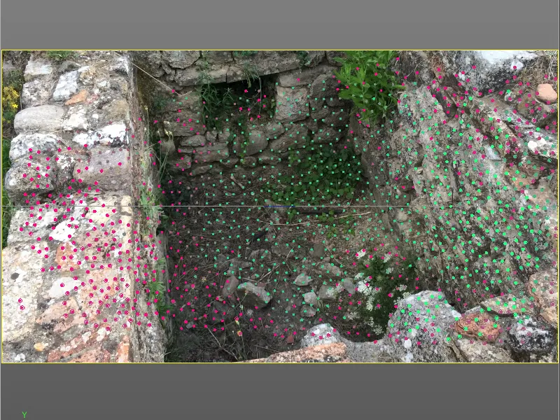
Calibrating the scene
Before we start the scene reconstruction, we calibrate the scene with constraints. Although this step is theoretically not absolutely necessary for the reconstruction, it immediately brings the scene to a usable reference point (origin) and to a correct axis position and scaling.
To ensure that we reach the best tracking points for this step, we set the time slider to a late point in time, which guarantees us high-quality tracking points.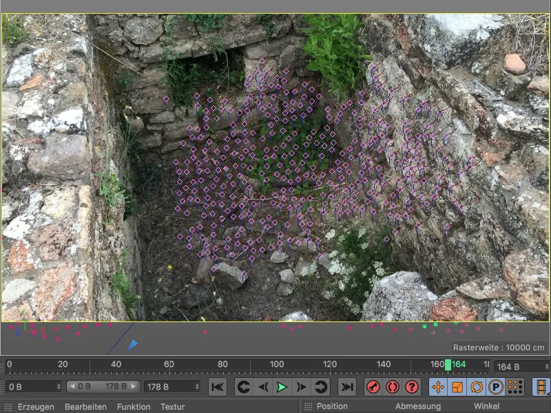
We start by determining the origin of the scene. To do this, we assign a position constraint to the motion tracker objectvia the Motion Tracker>Constraints menu.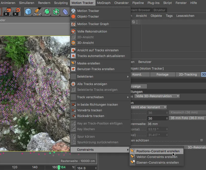
To declare a tracking point as the origin of the scene, we click on a tracking point in the middle of the floor with the active position constraint tool. The thick, orange border around the tracking point indicates that the origin has been defined.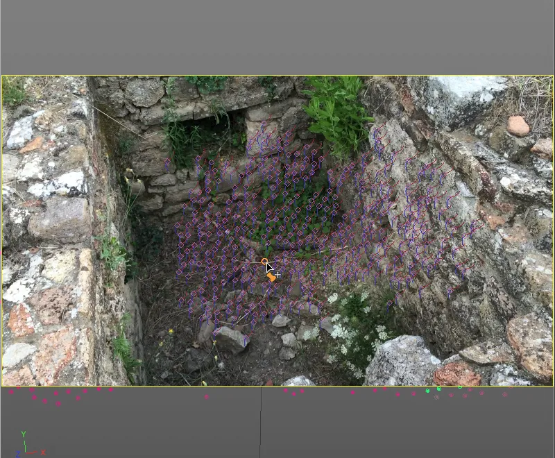
We can make sure in the settings dialog of the position constraint tagassigned to the motion tracker objectthat the scene origin we have selected is bound to a high-quality feature target (here: Auto 0661), because it is colored green.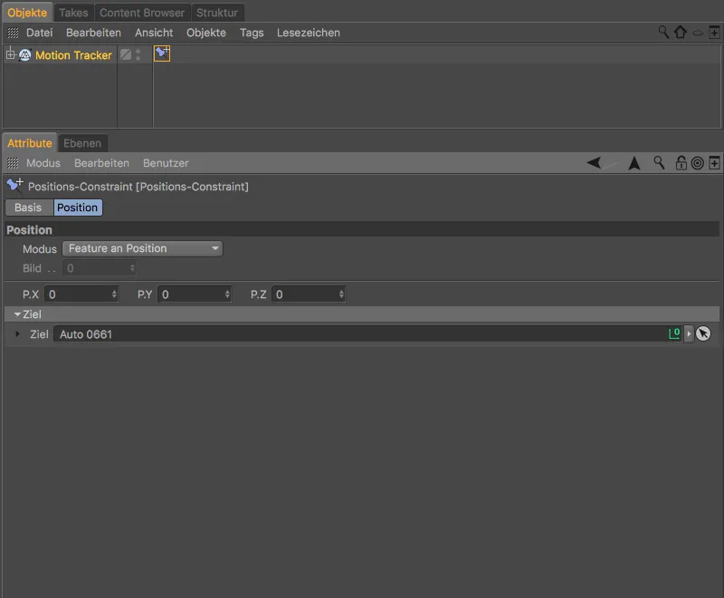
We continue with a layer constraint from the Motion Tracker>Constraints menu, which we want to use to define the alignment of the Y-axis.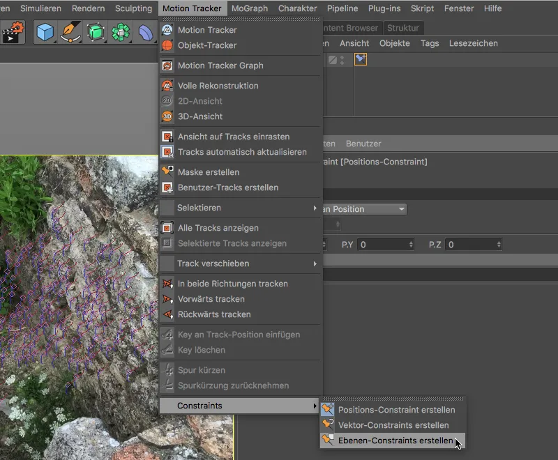
With the plane constraint tool now active, we draw a triangle by clicking over three tracking points on the floor plane. Always keep an eye on the alignment of the axis shown. You can use the Move toolto subsequently select the triangle points and place them on other, possibly more suitable tracking points as a test.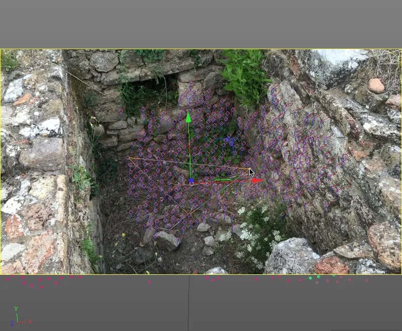
If you are satisfied with the result so far, we only need to define the desired axis for the layer constraint. This is done in the settings dialog of the plane constraint tag, where we select the Y-axis.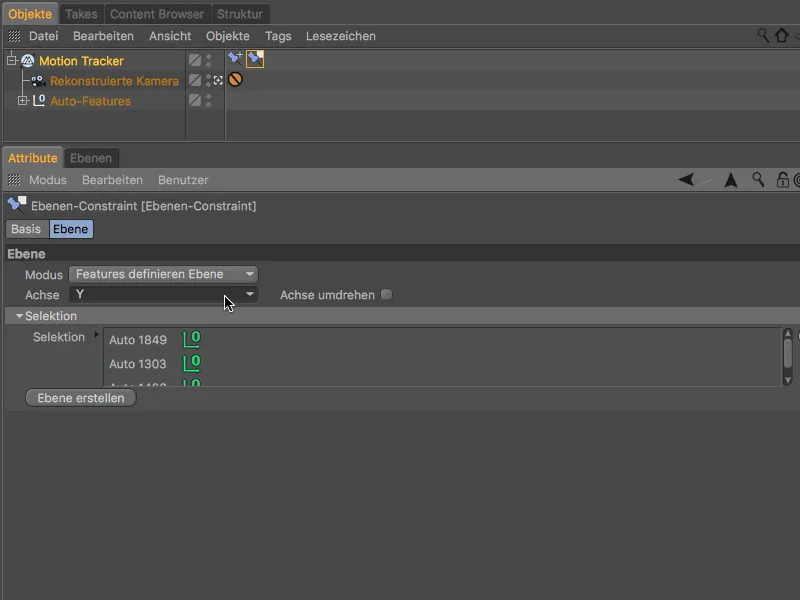
In the last step of the calibration, we define the alignment of the Z-axis and the scaling of the scene at the same time. To do this, we get a vector constraint from the Motion Tracker>Constraints menu.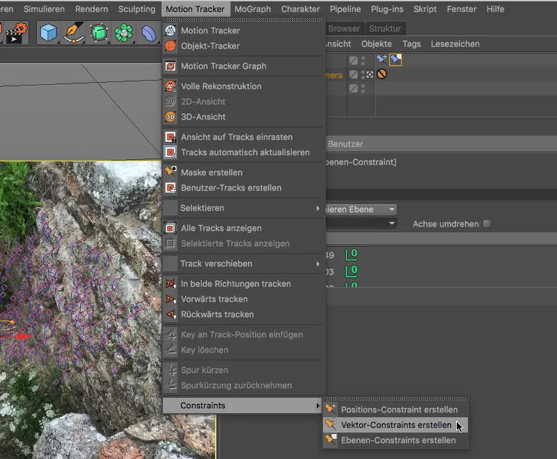
By creating the vector constraint, we have obtained a line in the 3D view, which we move to two suitable tracking points on the right wall to define the position of the Z-axis.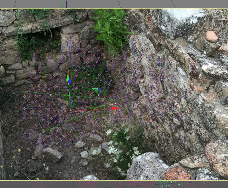
Once the line has been positioned over two tracking points parallel to the course of the wall, we open the settings dialog of the vector constraint tagand specify that the vector constraint line defines the Z-axis.
To take this opportunity to scale the scene, we set the specified length to Known and enter an estimate for the length of the line (in my case 1.5 meters).
As we can see from the green coloring of the two line targets, these tracking points are also well suited for calibration.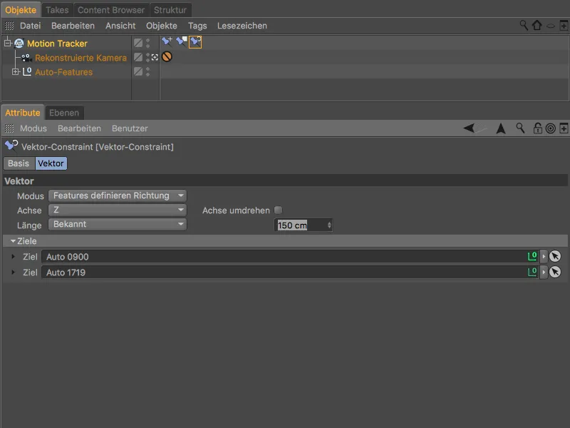
After completing the calibration, let's briefly switch to the editor camera by clicking on the small camera symbol next to the reconstructed camera in order to view the scene reconstructed up to this point.
As desired, the floor of the wall is on the XZ plane of our world coordinate system. Given the unevenness of the ground and the fact that the wall is certainly not really vertical, we can be quite satisfied with this result.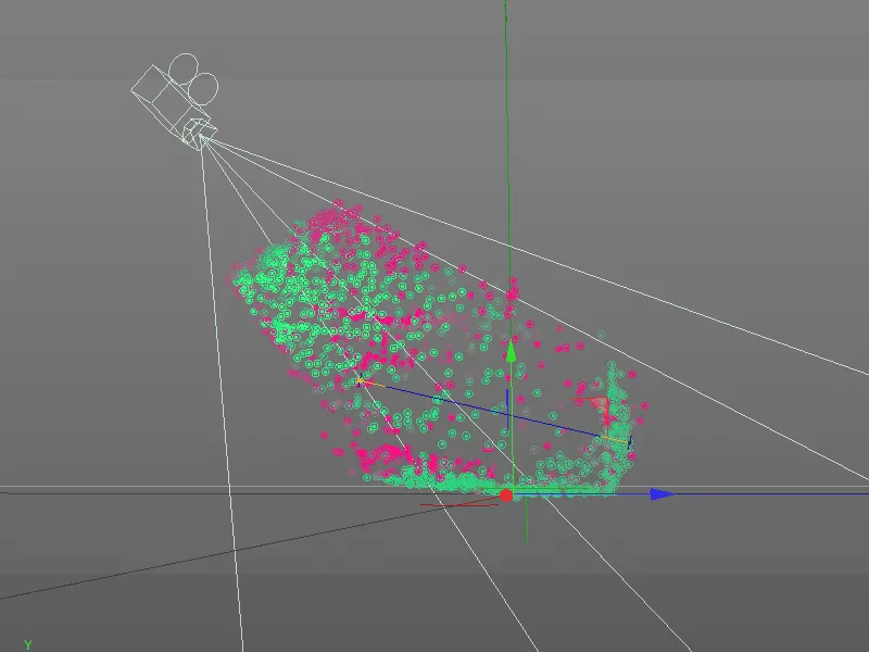
3D reconstruction of the brickwork
Now that the preparatory work has finally been completed, we come to the actual innovation in Release 19, the reconstruction of the scene on the basis of the 2D film data.
To do this, we switch to the last page of the settings dialog of the Motion Tracker object, to Reconstruction. Here we first select the High quality preset, which we immediately adjust to our requirements.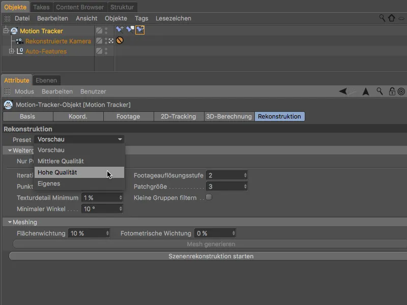
The scene reconstruction is divided into the creation of a point cloud and the subsequent meshing, the conversion of this point cloud into a polygon mesh. Both would run automatically one after the other, as we have selected the High Quality preset. However, as we only want to obtain the point cloud first in order to check it before meshing, we activate the Point cloud only option before we start the reconstruction by clicking on the Start scene reconstruction button.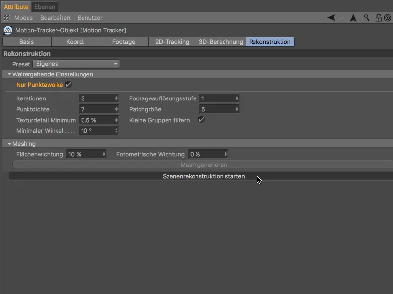
Depending on the speed of the computer, it may take a few minutes until a polygon object with a scene point cloud is created after the scene reconstruction is complete. This point cloud objecthas a vertex color tagthat conveniently shows the individual points of the point cloud with the reconstructed color information.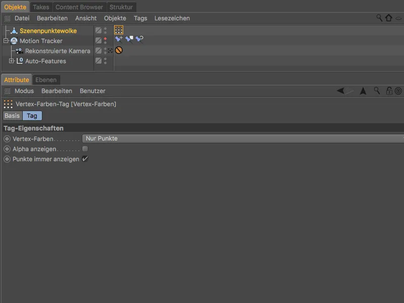
In the editor camera view, this colored point cloud alone provides us with very meaningful information about the reconstruction and the expected meshing.
In this case, of course, we cannot be satisfied with the result. Nothing at all can be seen of the rear wall, the floor only appears in isolated fragments - we have rightly saved ourselves the meshing.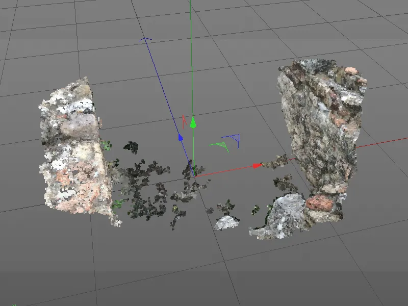
We therefore have to adapt the settings for generating the point cloud to the requirements of our footage. Firstly, we reduce the minimum angle to 2° to help the reconstruction of the left and rear walls. This compensates for the problem of the acute angle on the left wall and the low camera movement.
By increasing the patch size to 30, we achieve a larger search pattern, which increases the quality of the point cloud. Finally, we deactivate the Filter small groups option to prevent small but important patches from being filtered out.
We delete the polygon object of the old point cloud in the object managerbefore we start again by clicking on the Start scene reconstruction button.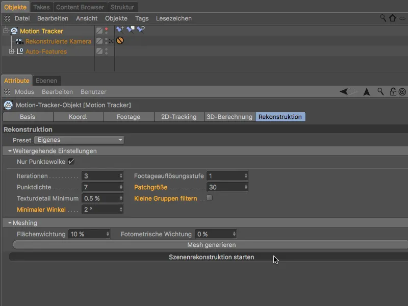
The creation of the point cloud will take a little longer due to the changed reconstruction parameters, but the result speaks for itself.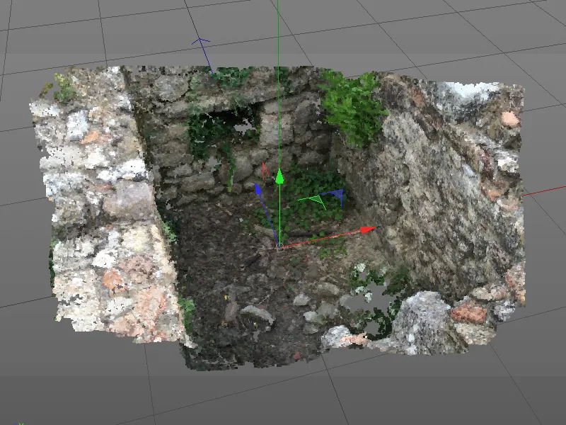
The floor and the rear wall are now also present, but it is not possible to get any more out of the left wall due to the poor camera angle. However, this is not too dramatic, as no filigree mesh is needed for areas that are not or barely visible.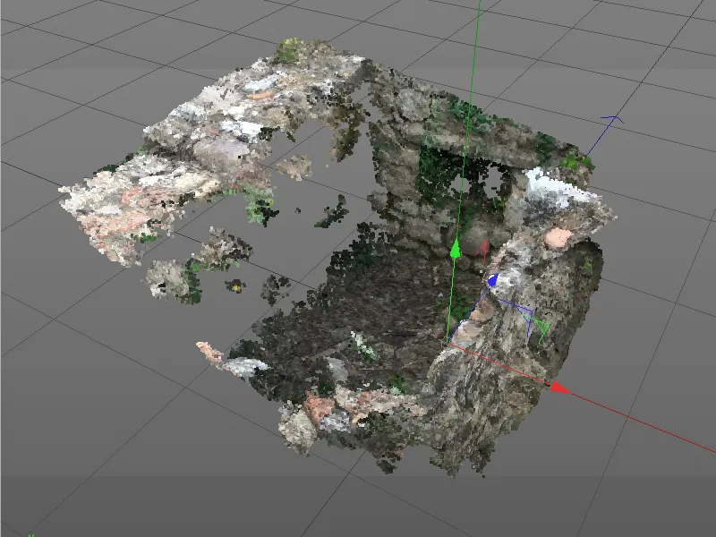
Successful meshing can be achieved with this point cloud. To start processing the point cloud into a polygon mesh, we click on the Generate mesh button in the Meshing section of the Reconstruction page.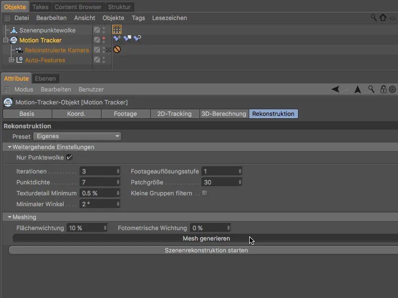
This process step is also somewhat time-consuming due to the high quality set, but after waiting a few minutes at the latest, we are presented with a polygon mesh that is closed almost everywhere.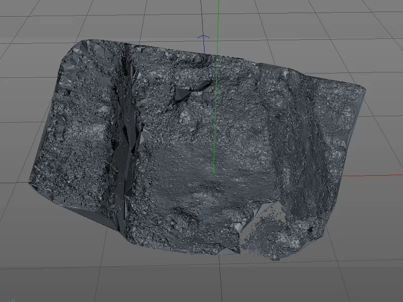
A new polygon object was created for the reconstructed scene mesh . As we are now going to continue working with this object, we can deactivate the visibility of the scene point cloud and - if not already done - the motion tracker objectin the editor viewusing the traffic light switches in the object manager.
As the scene mesh objectalso has a vertex color tag, ...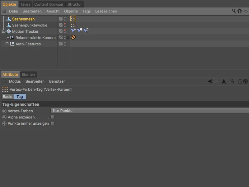
... we see the reconstructed mesh colored with the footage when we select the vertex color tagin the Object Manager.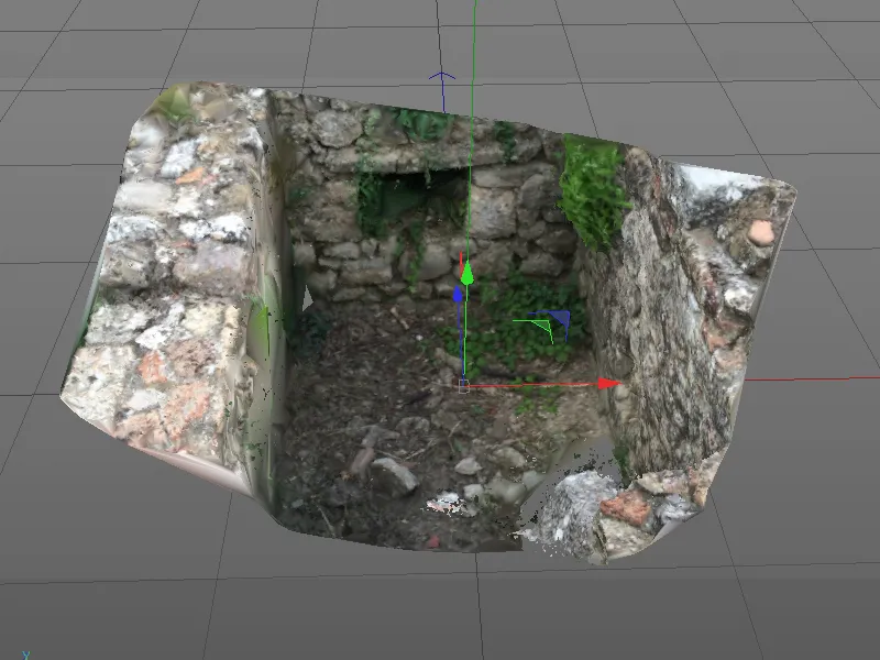
Here the problem areas of the reconstruction due to the color distortions already discussed become clear once again. However, we are only interested in a simple polygon mesh of the wall, which is why we can safely disregard this.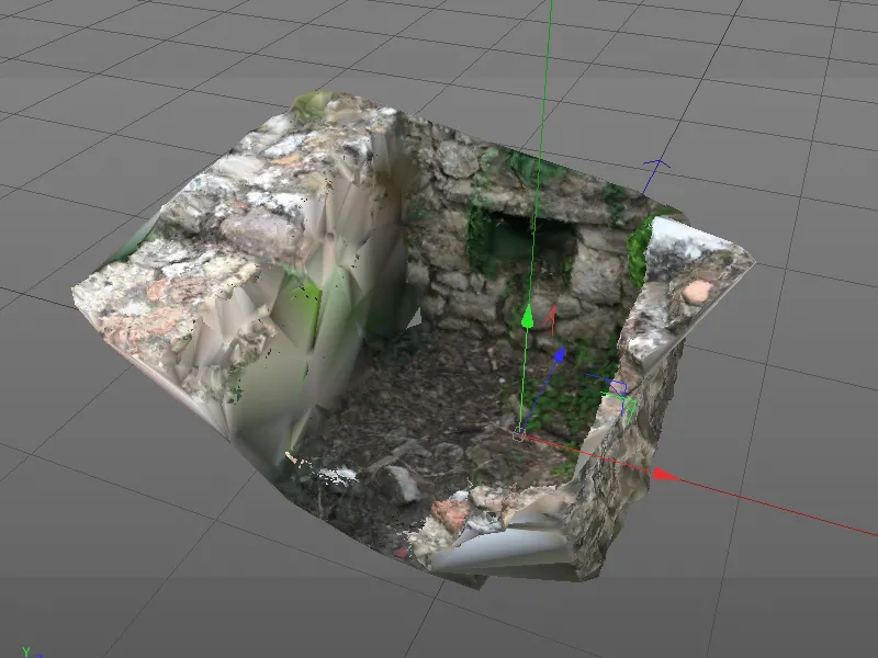
What we should not ignore is the small polygon hole in the back left corner. To close this hole, we select the polygon object of the scene mesh and call up the Close polygon hole tool from the Mesh>Create menu.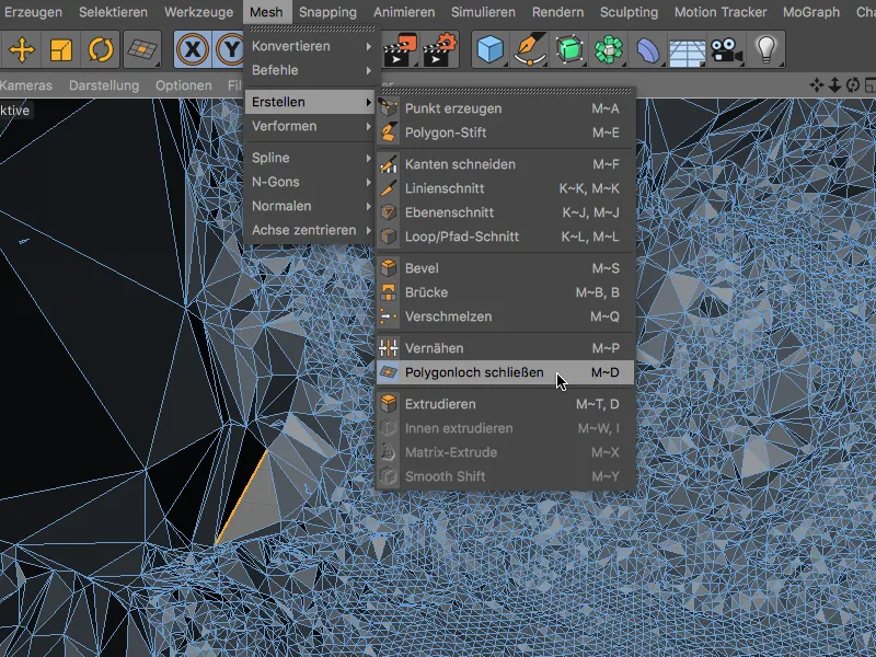
This tool recognizes the disturbing hole in the scene mesh as soon as we move the mouse pointer over an adjacent edge and closes the hole as soon as we click on it.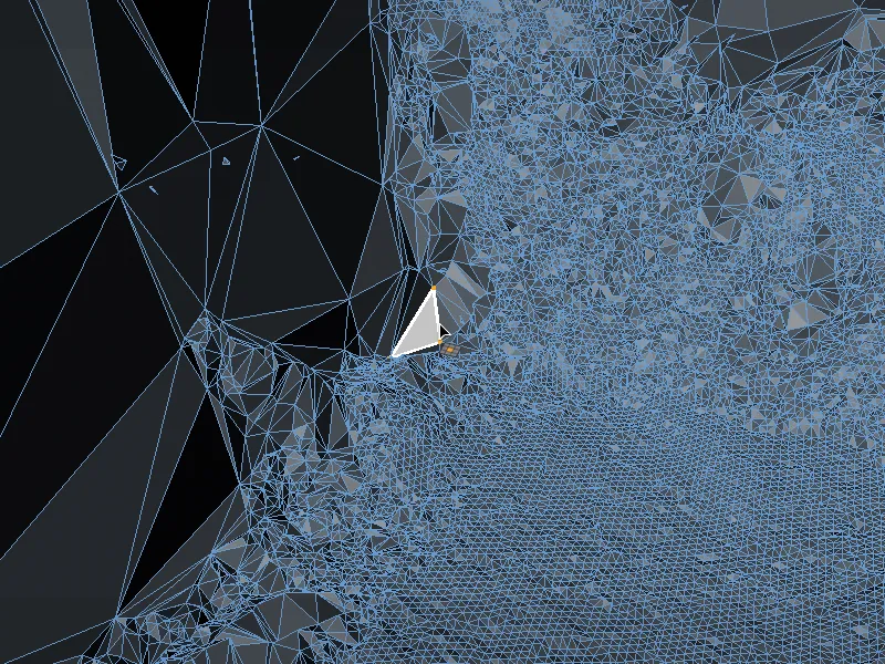
Smoothing the polygon mesh
The high resolution of the scene reconstruction is naturally also reflected in a very uneven mesh surface. If we were to simply place the polygon object of the masonry in a subdivision surface generator for smoothing, the scene would only become more complex due to the additional subdivision of the mesh.
Instead, we select the polygon object and, holding down the Shift key, call up a smoothing deformer from the Create>Deformer menu.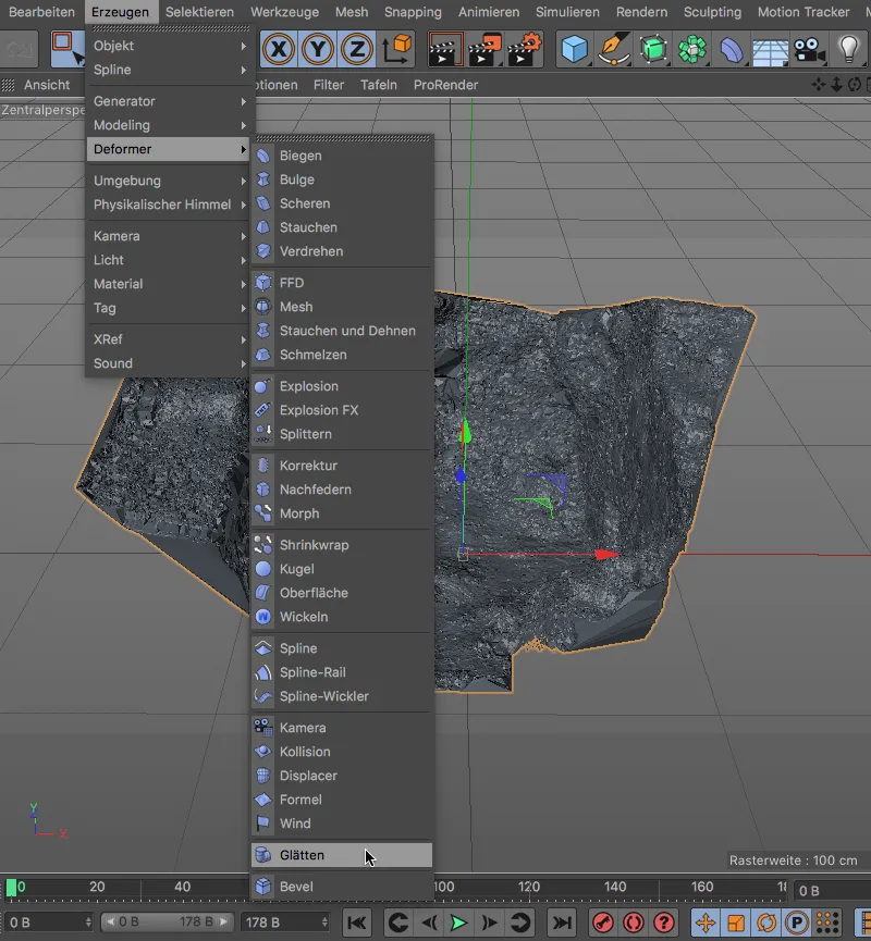
By adding the Shift keyas a modifier key, the smooth deformer has been subordinated to the scene mesh polygon object as required.
We can leave the settings of the smooth deformer at the default values.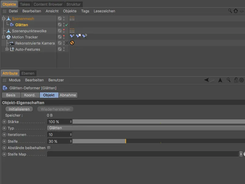
This makes the polygon mesh look much better. Our goal of the tutorial, the scene reconstruction of a wall, has now been achieved. Now let's take a quick look at how we texture the polygon object and integrate it into the 2D movie.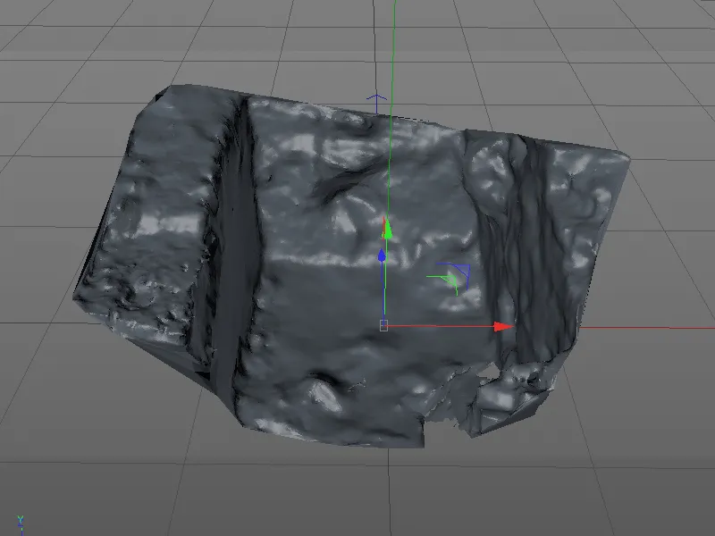
Integration of the 3D polygon object into the 2D movie
To integrate the reconstructed wall into the tracked film as a 3D object, we must firstly provide the 2D film in the background and secondly apply a frontally projected material texture to the wall.
To do this, we open the settings dialog of the motion tracker objectand switch to the footage page. Using the Create background objectbutton, we create a ready textured background objectfor fading in the 2D film in the rendering.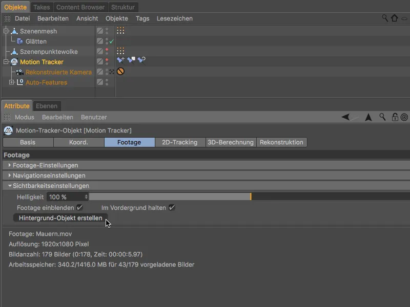
We can now also use the texture tagof the background objectfor the scene mesh objectof the wall. By dragging the texture tagwhile holding down the Ctrl key, we copy it to the scene mesh object.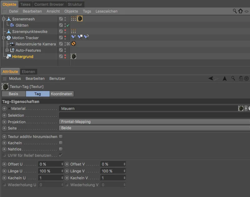
To ensure that the brickwork can receive shadows from other objects but cannot cast shadows itself, we assign a render tagto the scene mesh via the Tags>Cinema 4D Tags menu in the Object Manager.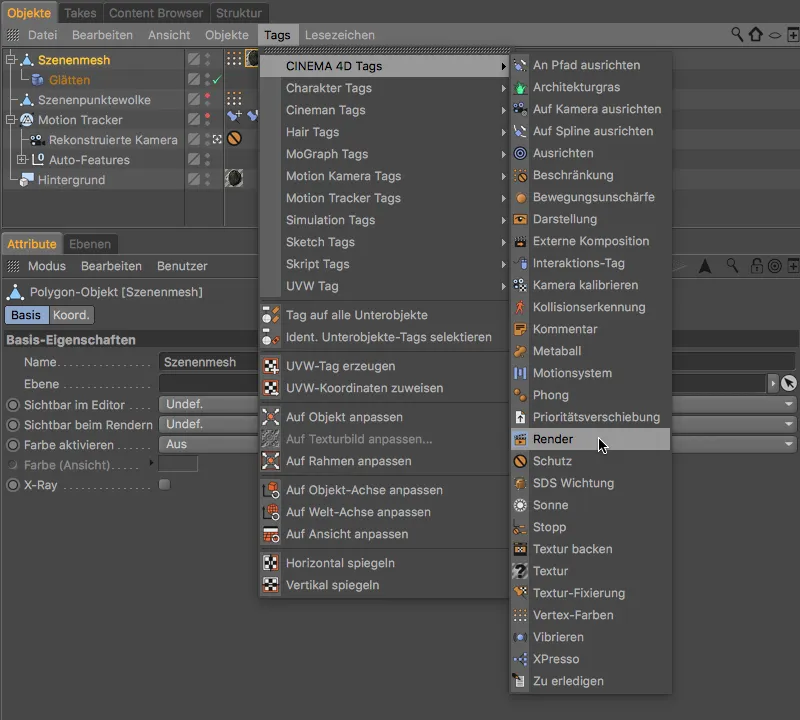
In the settings dialog of the render tag, we deactivate the Cast shadows option accordingly and activate the Background compositing option.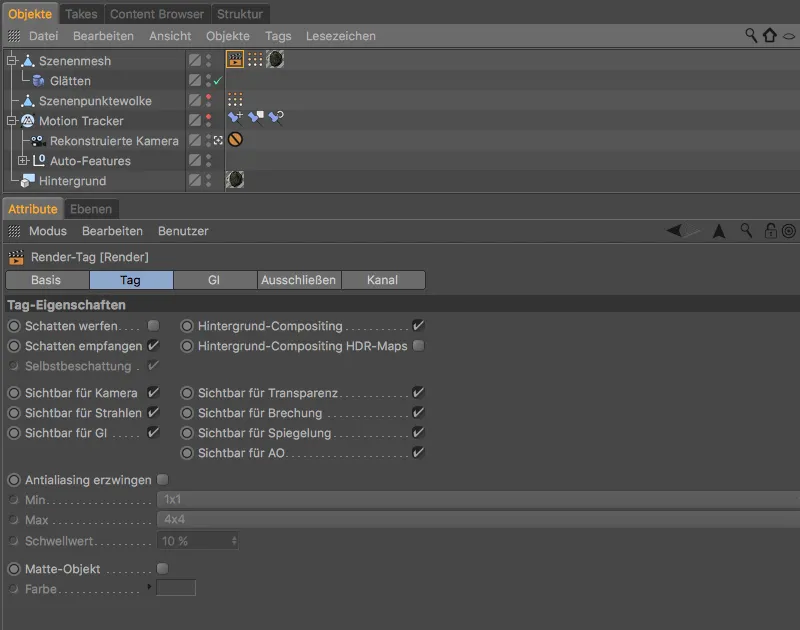
Now we can place any 3D objects in the wall, equip the scene with at least one shadow-casting light ...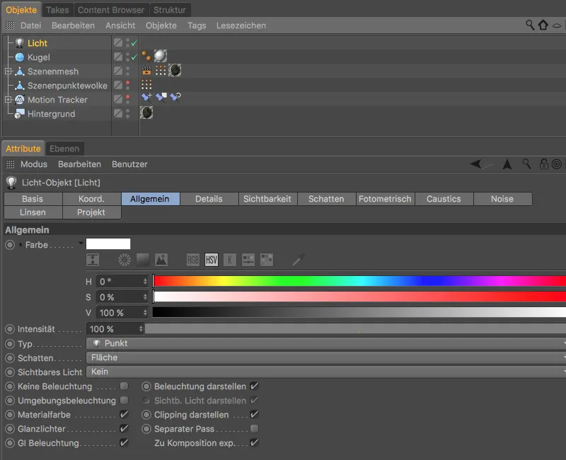
... and the wall will receive shadows in the correct places. Motion tracking also ensures that every integrated 3D object remains in the correct position in the reconstructed 2D film.