The original knife tool, which was previously also accessible via the keyboard shortcut K, no longer exists as such. The new three knife tools Line cut, Layer cut and Loop/path cut can of course still be found in the Mesh>Create menu.
As you can see from the menu, the three knife tools can each be called up via two hierarchical keyboard shortcuts. Either together with the other modeling tools via the M key ...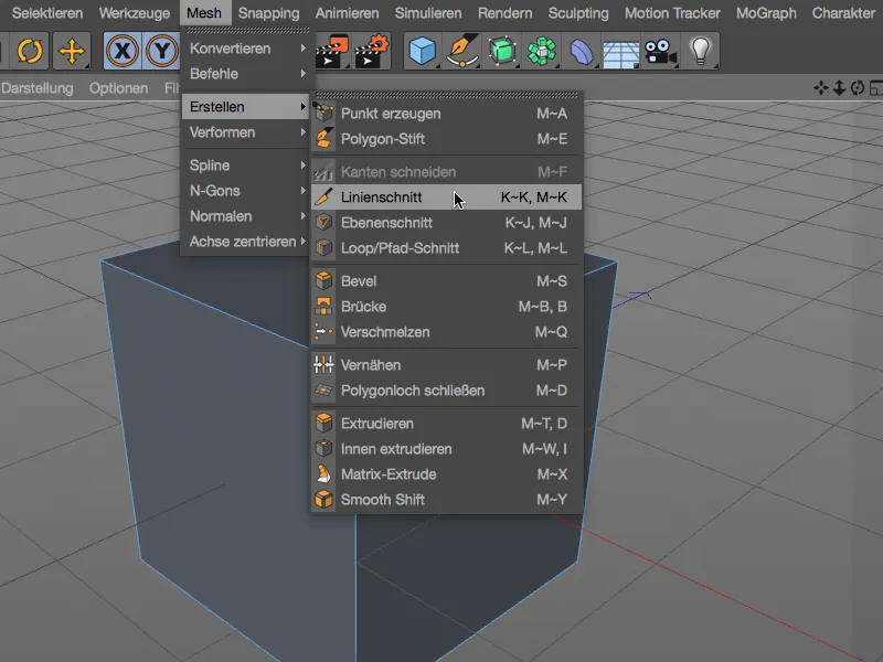
... or, as anyone who is familiar with the K key for the knife tool will know, via the new hierarchical keyboard shortcuts for the knife tools.
Now let's take a look at the three tools in detail. For a better overview, I am using a simple polygonal cube, as the cuts are very easy to follow here.

Line cut
With the line cutter, you can cut polygon objects or spline paths by setting control points for the cutting line in the view. The cutting line remains active and editable until you confirm the cut by changing the view, pressing the ESC keyor changing the tool.
The colors of the control points indicate whether the point is outside the object (yellow), on a point (green), on an edge (red) or on a polygon (blue). The intersection points on the edges created by the cuts are marked in white.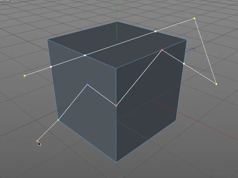
The new knife tools have their own snapping functionality, which automatically snaps to points, edges and polygons when moving control points, in contrast to the standard snapping with corresponding colored feedback.
When moving with the Shift keyheld down, the respective point follows the adjacent edge. To delete a control point, simply click on the point as usual while holding down the Ctrl key.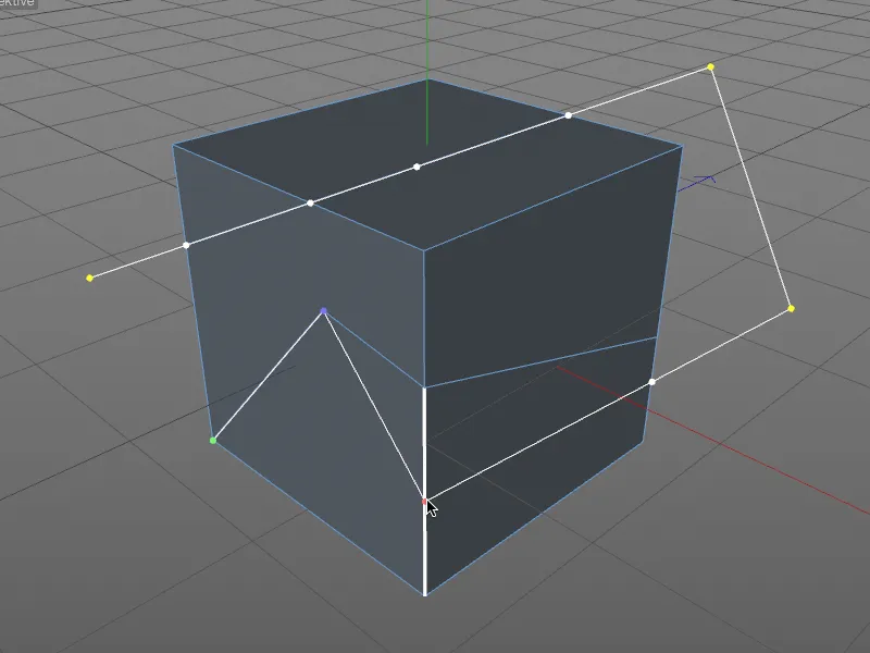
Now let's take a look at the settings dialog of the line cutting tool. Here, in addition to a few additional cutting options, we find the aforementioned auto-snapping and the option to restrict the angle. This can also be activated interactively before setting a control point by holding down the Shift key.
Of particular interest, however, is the Cut mode menu, in which the type of knife cut can be defined. We achieve the usual adding of points via the Cut option, while Separate splits the object into two separate parts - the cutting points are therefore created twice.
The Remove part A and Remove part B modes not only separate at the cutting line, but also delete the respective half of the object directly.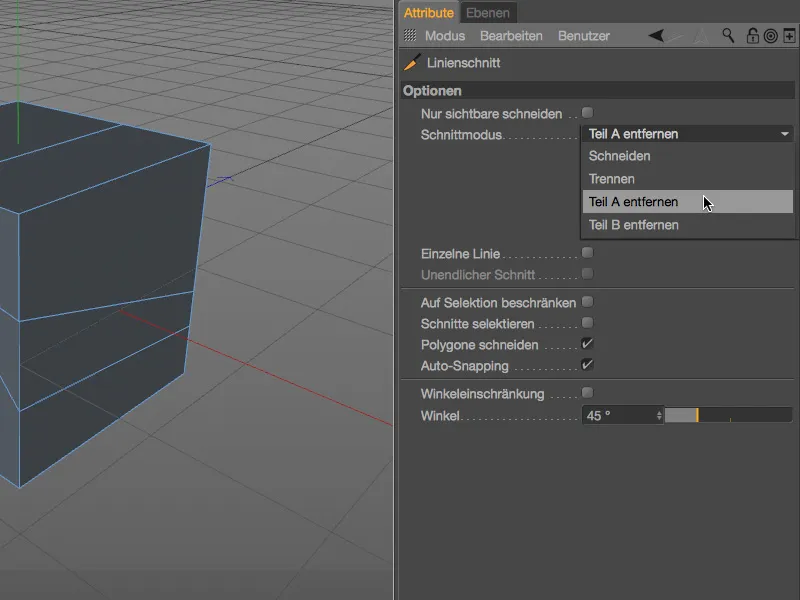
There is no clear logic behind the definition of part A or B - if the wrong object part is deleted, simply use the corresponding other mode. It is also advisable to set the control points of the section outside the object in order to define a clear section.
A special feature of the line cutting toolis the ability to create cuts based on projected spline paths. In the example shown, consisting of a polygon pyramid and a star spline object, the spline path should intersect the polygon surfaces by vertical projection.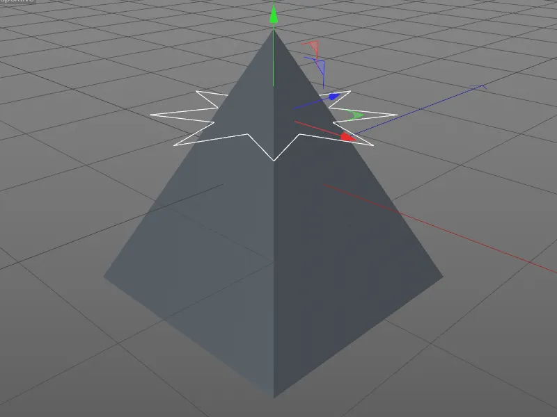
For the vertical projection, we must first switch to the view from above ( F2 key ). We then select the pyramid in the Object Managerand activate the line intersection tool( K - K keys ). Now just click on the spline path while holding down the Ctrl key to create a star-shaped section on the pyramid.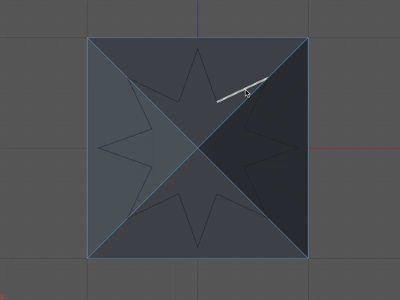
Back in the central perspective ( F1 key ), we can see the cuts created by the star spline on the pyramid. For better visibility, I have selected the new polygons lying in the star.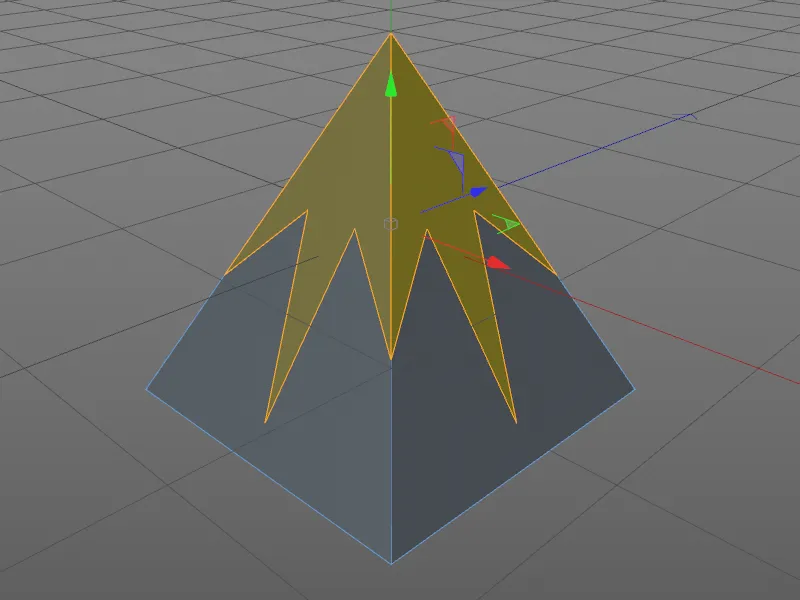
Layer cut
Let's move on to the second cutting tool in Cinema 4D Release 18, the layer cut. The quickest way to access it is via the hierarchical keyboard shortcut ( K - J keys ).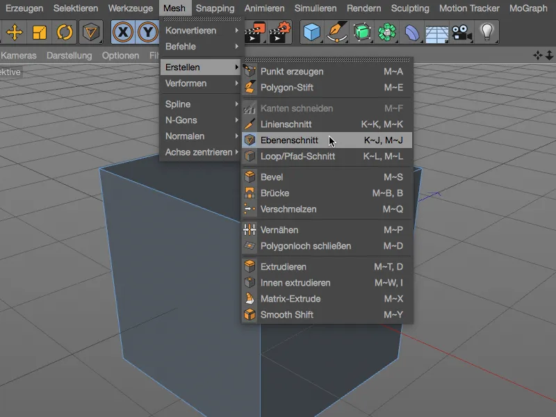
Layer cuts are of course nothing new in Release 18, but the new handling is all the more impressive. In the settings dialog of the layer cut tool, the layer mode is of crucial importance. The Local, World and Camera modes are familiar and create sections in the additional coordinate plane to be defined.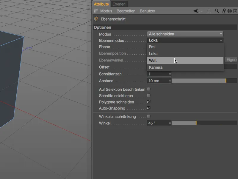
In the editor view, a white layer border shows us a preview of the layer cut that can be executed with a click. So far, so familiar.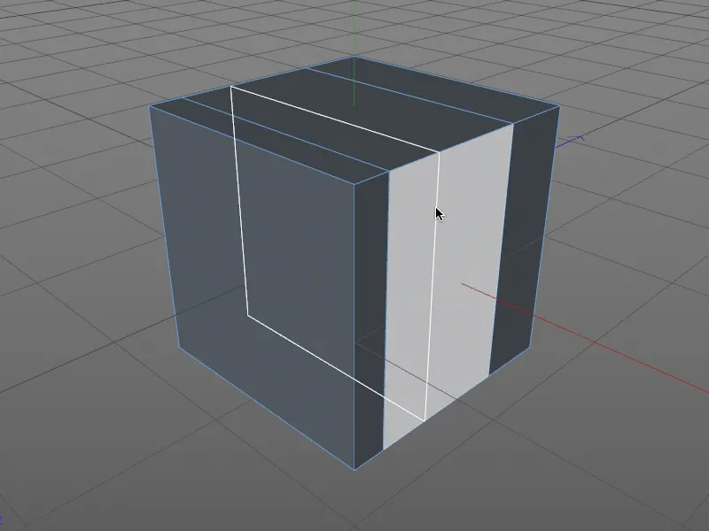
Much more interesting is the Free layer mode, which enables the layer position and angle parameters in the settings dialog. Similar to the line cut tool, the cut, snapping and angle restriction options are also available for the layer cut.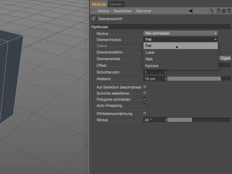
For the free cutting plane, we create a cutting line in the editor view by creating two control points. The section plane is parallel to the viewing direction on this line.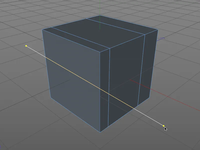
As soon as we rotate the view slightly, we not only see the section plane created in the object better, we also get a position and rotation manipulator. We can use it to determine the adjacent free section interactively in the editor.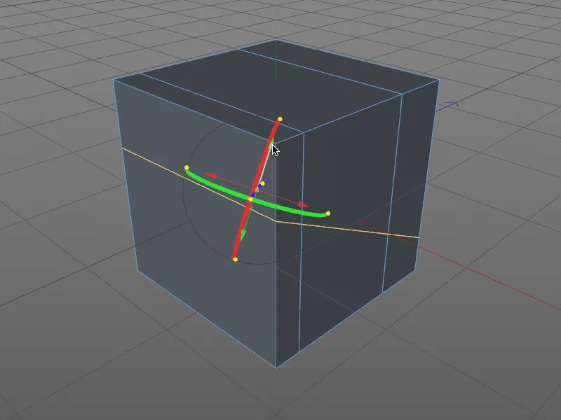
To make it easier to understand, X-Ray mode is activated for the view in this illustration. The outline of the cutting plane is now also visible on the hidden edges. Dragging the position starters or turning the rotation bands is enough to control the layer section in the editor.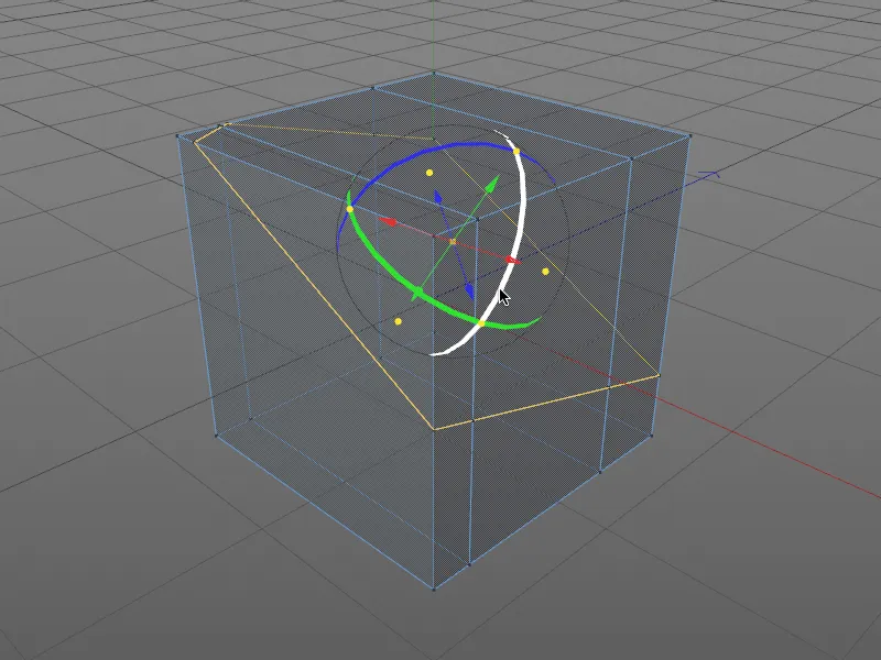
However, as already mentioned, the layer position and angle of the layer section can not only be controlled interactively in the editor, but also via the settings dialog in the Attribute Manager. The position and rotation manipulator therefore also appears as soon as we modify one of these parameters.
In addition to the position and angle of the layer, the settings dialog of the layer cut toolalso offers the option of applying several cuts at a specified distance.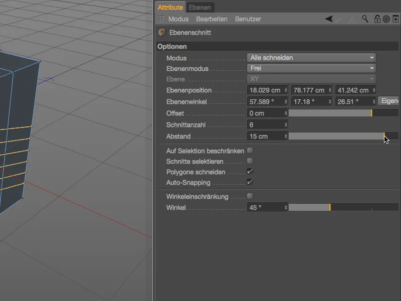
The orange-colored handles of the plane cut manipulatorshould not be forgotten. The handles at the end of the axes allow the plane cut axis to be rotated freely in the editor. The handle at the origin of the manipulator, which allows you to freely move the entire layer section while maintaining the same alignment, is somewhat less recognizable. The following applies to all handles: Auto-snapping on points, edges and polygons works of course.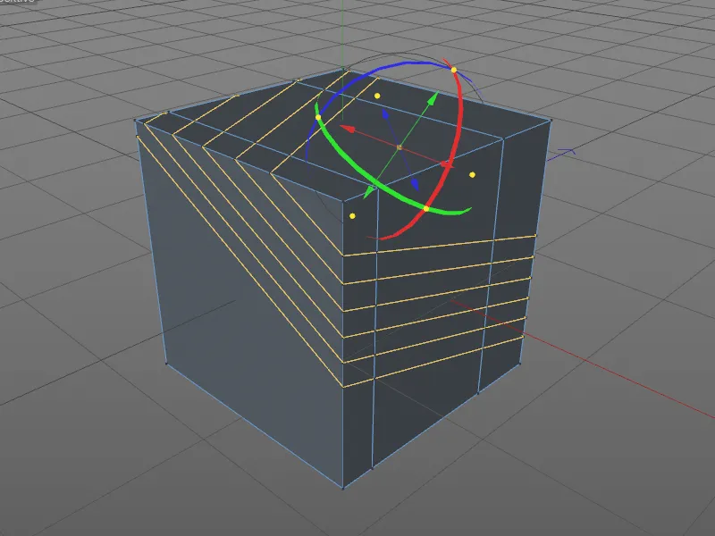
For the layer cut tool, the Cut mode parameter in the settings dialog also offers us the option of cutting, dividing or even removing a piece of the object.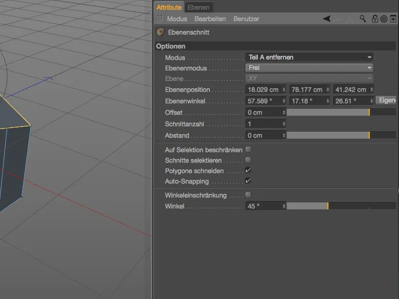
Together with the position and angle manipulator, this makes it very easy to create interactive sections on models.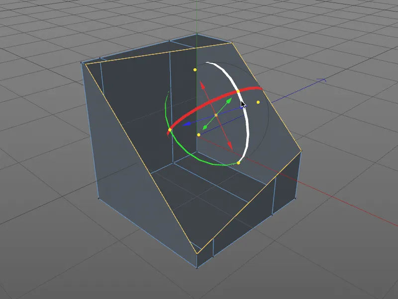
Loop/path cut
The third new knife tool, Loop/Path Cut, can be accessed via the shortcut ( K - L keys ). In contrast to the other two cutting tools, it can be used, for example, to refine the subdivision of special areas of a model, such as edge loops.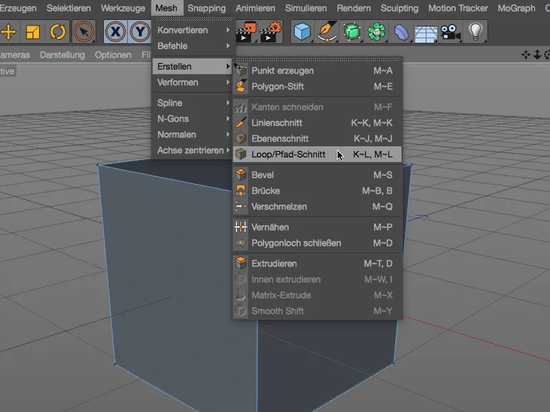
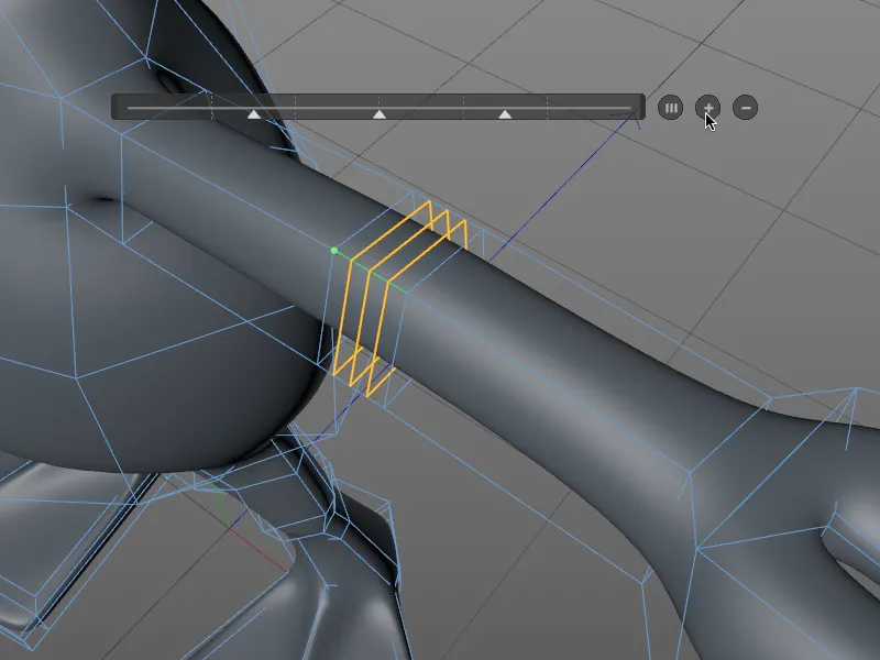
First, however, we will return to our polygon cube to look at the basic function of the tool. Immediately after calling up the tool, we notice the HUD bar above the object to be cut. We can move it to any position in the editor with the mouse pointer and adjust its length as required using the two handles on the left and right.
If we now decide on one of the edges suggested by the loop detection, to which the loop cut is to be made perpendicularly, and create a first cut, the percentage position of the cut in relation to the total length of the green-colored edge is displayed in the HUD barwith a triangle as a slider.
The specified offset value can be set by moving the slider, but can of course also be entered directly by double-clicking on the slider value.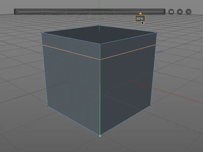
If you don't like working with crooked numbers but can do without the numerical input, you will find the option to quantize the subdivision in the settings dialog of the loop/path editing toolin addition to the now familiar editing options in the Interaction area.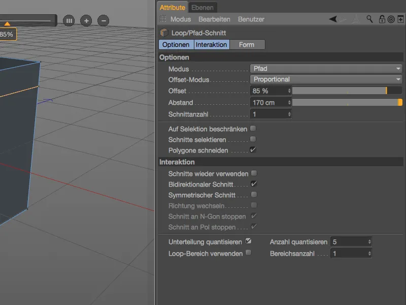
After activating this option, we are immediately shown the specified number of reference points for the next cut. For the second cut with the loop/path cutting tool, I decided to use the second quantization step from the bottom.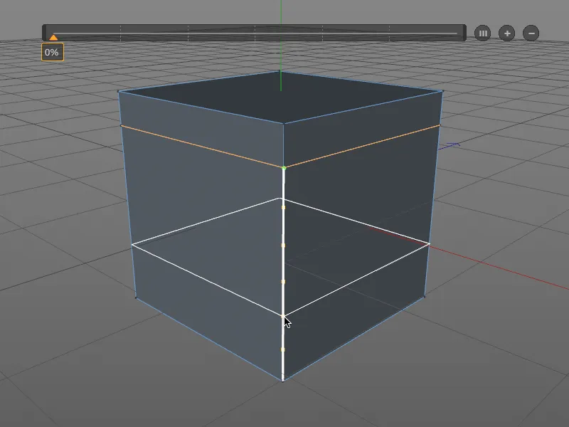
To test the possibilities of the loop/path cut toola little further, we place another cut between the existing edge loops (green marking).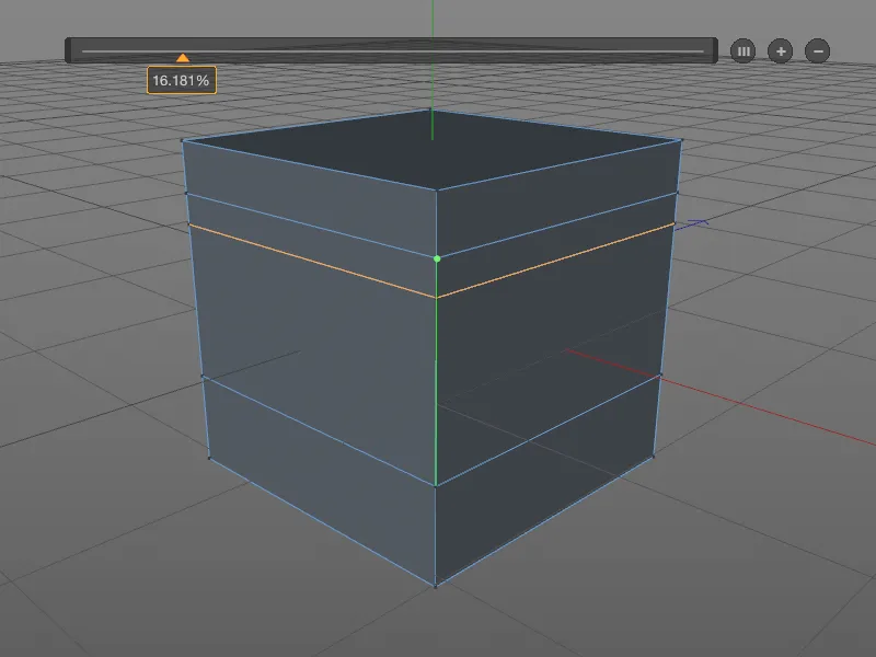
To create further subdivisions for the loop cut, we use the (+) button on the HUD bar. We get equally spaced subdivisions for our loop/path cut(s). Each section created can be modified either using the slider or directly with the mouse pointer on the object. If you want to distribute the distances evenly again, simply click on the button (III) in the HUD bar.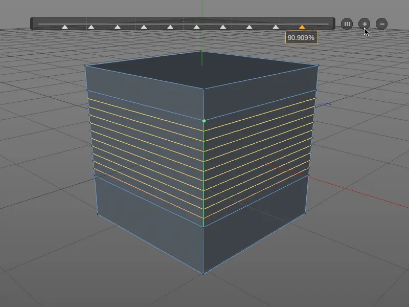
In the third area, Shape, of the settings dialog for the loop/path cutting tool, we now work out the shape of the applied loop cuts a little further. We activate the Use spline option to define our own profile for the shape . In the small curve editor, you can create your own curve or, like me, use one of the spline presets that can be selected via the context menu. We use the Extrude value to control the deflection of the shape we have defined.
For loop/path cuts on curved surfaces, the Preserve curvature option comes into play. The adjacent curvatures are then also taken into account for the loop/path cut.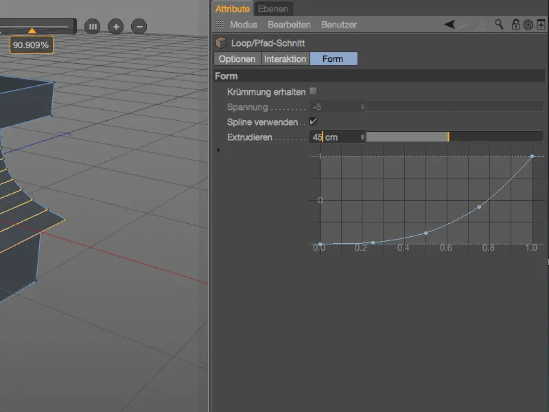
The spline curve we have created is clearly reflected in the shape of the loop/path section. And everything is still editable as long as no other tool is selected or the ESC keyis pressed.
Let's move on to a practical example in which the convenient creation of loop cuts is often required to specifically increase the subdivision. The example shows the crook of a character's arm, which has too few subdivisions for a later animation (i.e. deformation). The edge selection required for our loop/path cut toolis quickly created using the Ring selection tool from the Select menu.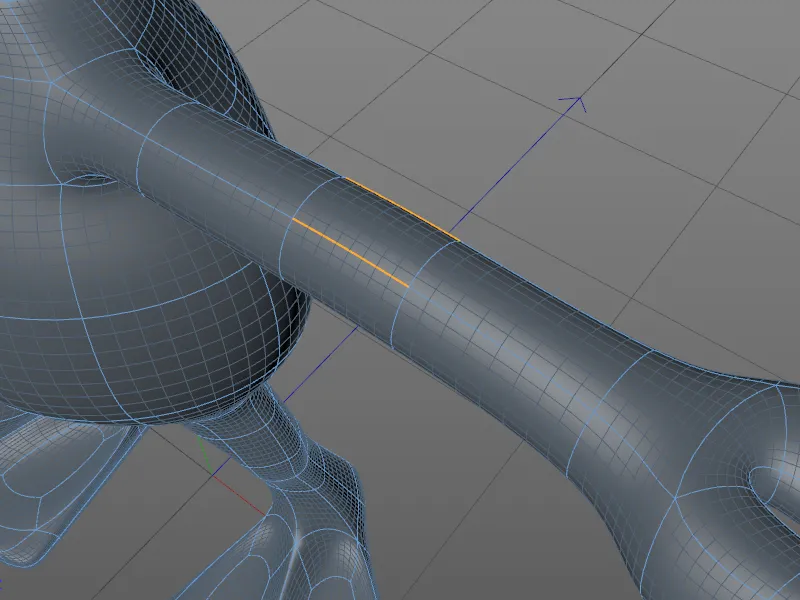
In the settings dialog of the loop/path cutting tool, we set the mode to Path this time, as the knife tool should not use loop detection, but should use the ring selection specified by us for the cut.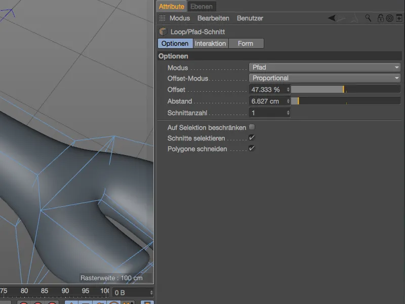
The number and distribution of the knife cuts for subdividing the object geometry can be set not only via the parameters in the settings dialog, but also conveniently via the familiar HUD bar.