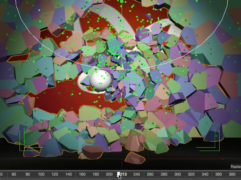
In this tutorial, we will bring down a wall by firing bullets at it, thereby revealing the PSD logo.
Setting up the scene
So that we don't have to spend time unnecessarily building up a few layers and lights, the package of working files includes our common starting point called "PSD_C4D_R18_MoG_Voronoi_Bruch.c4d".
Let's take a quick look at the structure of the scene from a lateral perspective. On the far right is a layer objectwith the familiar PSD logo of the butterfly. In front of it is a wall consisting of a simple cube object. The scene is illuminated by a spot light source as the main light and two dimmed fill lights. A camera is also already positioned, aimed directly at the wall, but also captures a piece of the floor object.
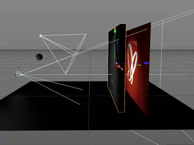
With the exception of the simple sphere, the parametric wall is the main actor in our animation. Because the Voronoi break objectis completely responsible for creating the break pieces, it can even remain a basic parametric object.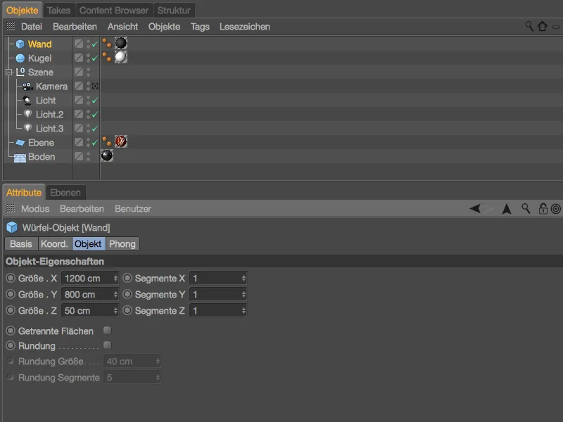
So that no objects in the scene that are not needed at the moment disturb us, we hide the sphere, the camera and the light sources using the traffic light switches or deactivation in the Object Manager.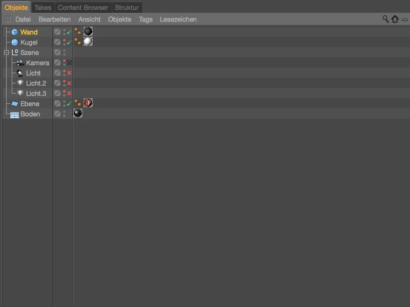
Installing and setting up the Voronoi break object
It is best to switch to the front view ( F4 key ) in order to have the cube objectof the wall completely in view in the editor view.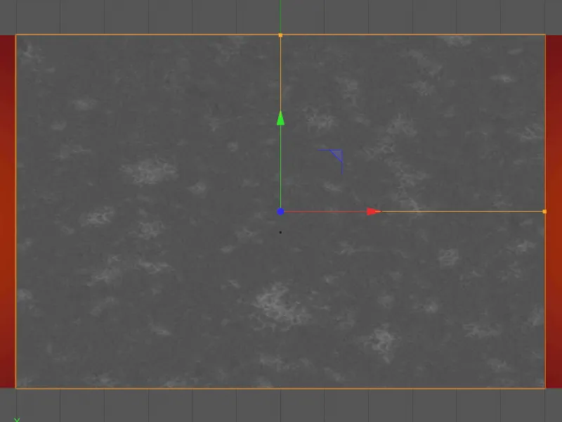
Make sure that the wall is selected and bring a Voronoi Fracture object from the MoGraph menu into our scene. Hold down the Alt keyto subordinate the cube objectof the wall to the Voronoi break object.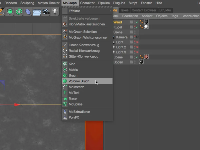
The cube objectof the wall is now divided by the Voronoi Fracture objectinto color-coded individual parts. The division is based on a point cloud, with the dividing lines lying exactly in the middle between two points. We will take a closer look at these points shortly.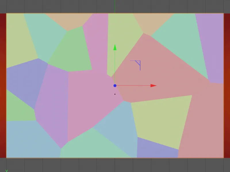
Before that, let's take a look at the settings dialog of the Voronoi break object. Here, on the object page, we find numerous options for adapting the break to the object. For example, we can control the fraction with selections and weighting maps, restrict the fraction to surfaces , define objects as hollow or sort the fractions using the index number.
To test how the current fragments appear on our wall, we temporarily deactivate the Color fragments option and specify a fragment offset of 20 cm.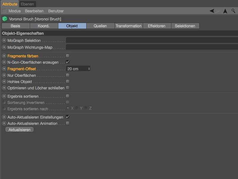
As you can see, you can use the fragment offset to adjust the gap between the individual pieces. Our wall is correctly divided according to the separation applied by Voronoi interpolation.
We set the fragment offset back to 0 in order to divide the wall into the fragments.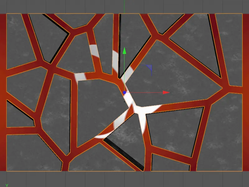
We can find all the settings relating to the division on the Source pageof the settings dialog. As already mentioned, the divisions are based on point information that the Voronoi Fracture objectcan receive from various sources.
By default, the Voronoi breakobject has a point generator as a distribution source, which we can adjust using the parameters below. However, as the second button suggests, shaders can also be used to create the divisions. But that's not all, in principle all point-generating objects in Cinema 4D, be it splines, polygon objects, generators or particle emitters, can be defined as a source by drag and drop.
Our first point generator is intended to provide the rough fragments in the wall. The existing even distribution of the pieces is sufficient for this, we simply increase their number and test a starting value that we like for the divisions.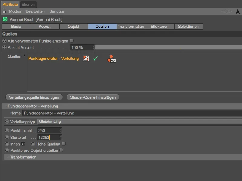
The larger number of points means that there are now more fragments, which are closer together due to the space available. The points whose interpolation results in the fragments can be seen in green.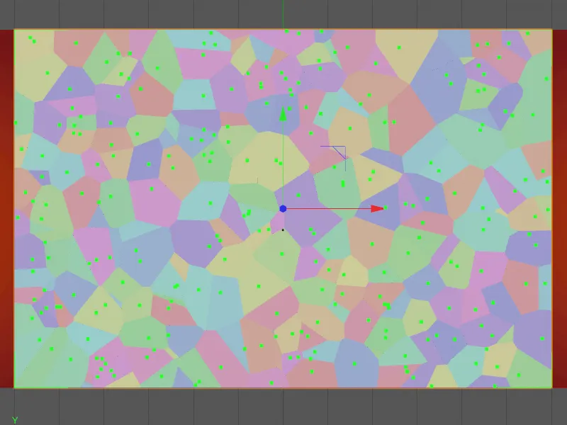
In order to be able to distinguish between the different distribution sources, we assign a meaningful name in the Name field, such as "Coarse" for the coarse division of the fragments. As the bullet or bullets will be fired at the center of the wall, we want to scale the width of this rough point cloud a little. To do this, we open the Transformation area in the settings dialog and assign a value of approx. 0.85 for the size in the X direction.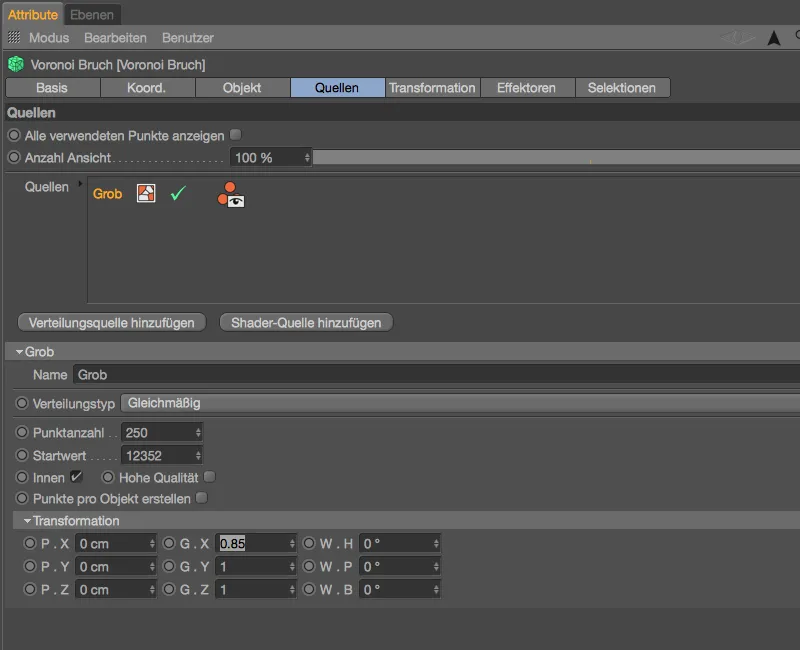
We can see that the point cloud is now slightly narrower. The number of fragments of course remains the same, but we have concentrated the fragments a little more exactly where the impacts should mainly take place.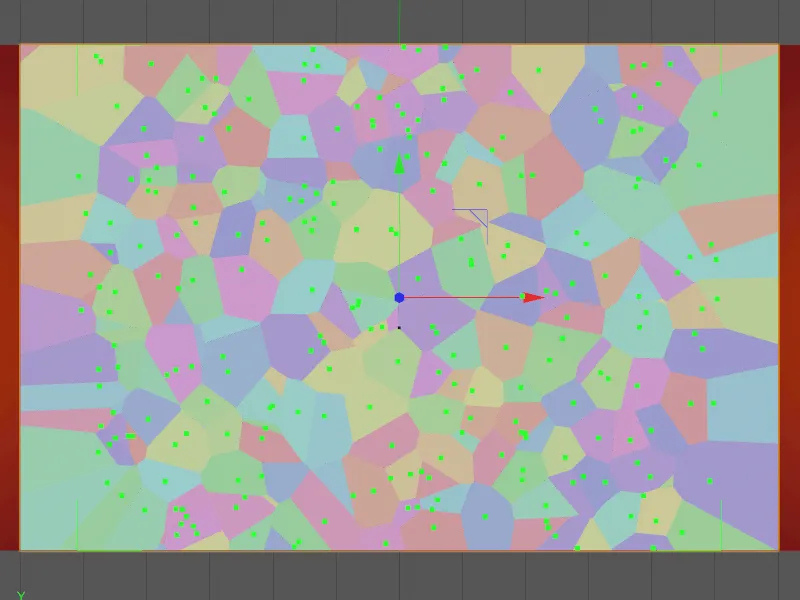
To add a little more detail to the predefined fragments, we create an additional point cloud by clicking on the Add distribution source button, but this time for the finer fragment structure.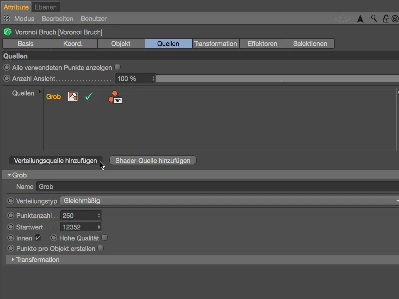
We immediately assign a suitable name such as "Fine" to this second distribution source. Instead of the uniform distribution type, this time we want to use a distribution that is more concentrated on the inside of the object; we achieve this using the Normal setting in the Distribution type menu. In contrast, we would use the Inverse-Normal variant for a distribution that pushes outwards into the corners of the object. The exponential distribution is based on a predefined axis.
The dimensions of the distribution are determined by a cuboid bounding box that encloses the respective object.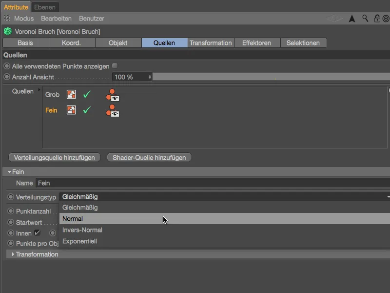
The standard deviation parameter is available to control the point cloud. Smaller values bring the points closer together, while larger values pull the points apart.
In order to obtain sufficiently small fragments, we set the number of points to 300, and again we can vary the division using the start value.
As we are now using more than one source to create the fractions, we also activate the Show all points used option.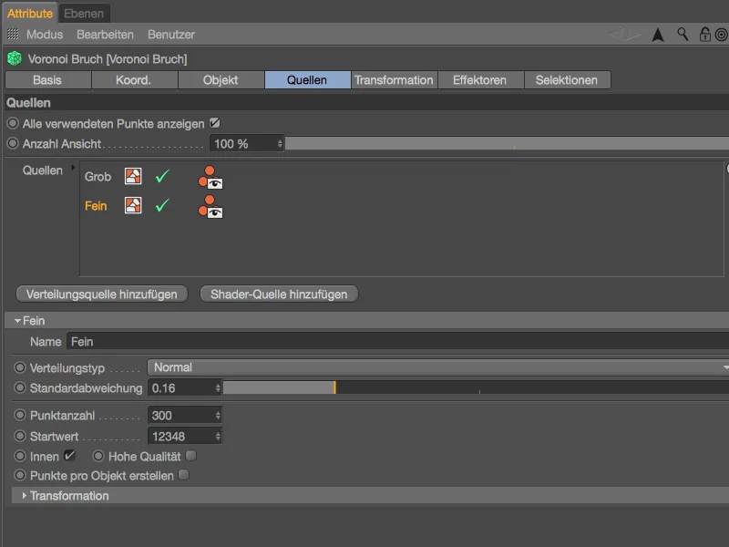
When we look at the editor view, we can see the dark green, coarse distribution source created previously in addition to the light green, fine distribution source for better orientation.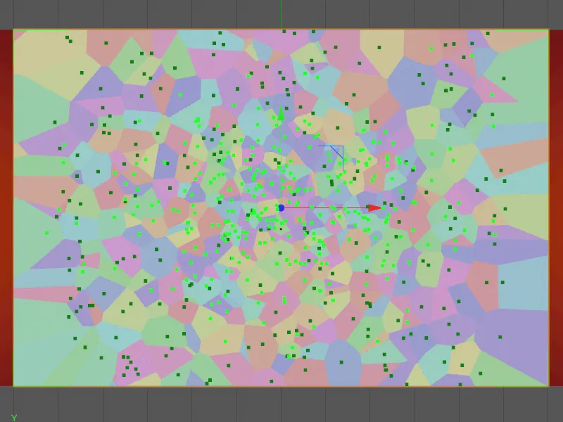
We also want to prepare this second, finer point cloud for the impacts using the transformation parameters. To get a better feel for the effect of the changes, you should experiment with the parameters. I have stretched the height and compressed the width of the fine distribution source using the size parametersand moved it a little to the bottom and left using the position parameters.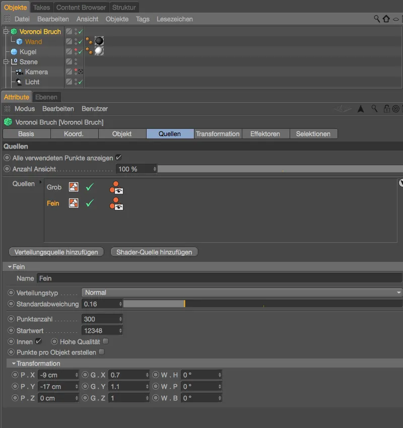
We can show the objects hidden via the Object Manageragain, as we have now completed the preparation of the fragments in the Voronoi fragment object. These two distribution sources should be sufficient for our purposes. The order of the source levels in the corresponding field is irrelevant.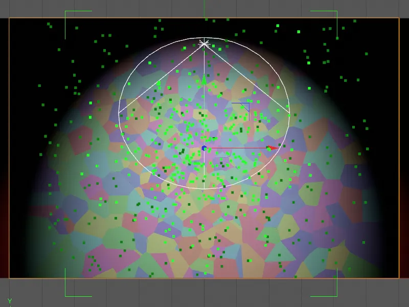
The green bounding box of the fine point cloud created from the cube objectof the wall and modified using the transformation parametersis clearly visible here.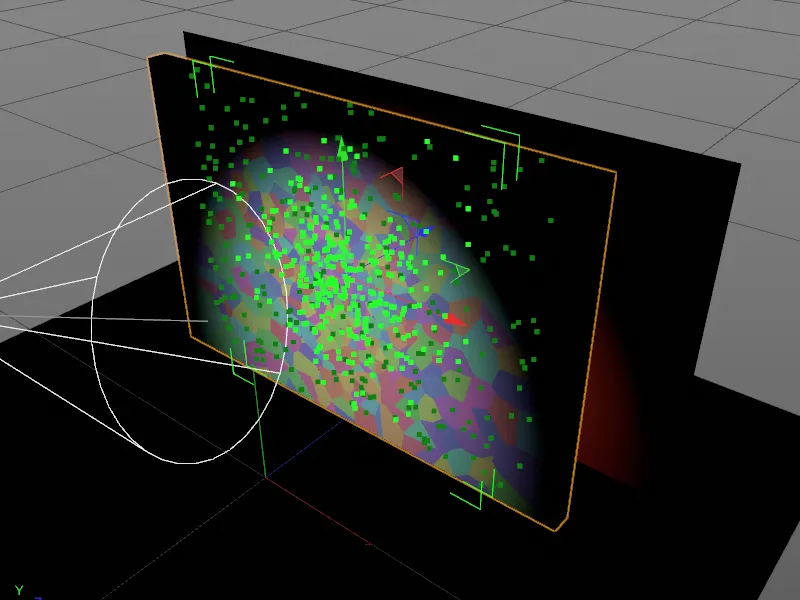
Features with dynamic properties
We will soon need the settings dialog of the Voronoi break objectagain, but in the meantime we will equip the objects involved in the simulation with dynamic properties.
The layer with the PSD logo and the floor may only generate collisions, so it is sufficient to assign a tag as a collision object to both objects via the Tags>Simulation Tags menu in the Object Manager.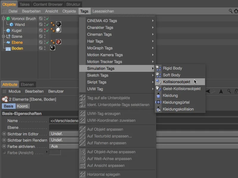
In the settings dialog of the two Dynamics Body tags as collision objects, we reduce the elasticity to 20% and increase the friction to 120%. As a result, the fragments do not jump far upwards and also remain on the ground without sliding far.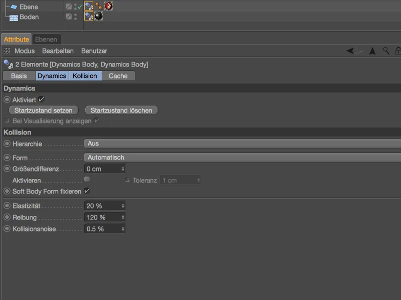
Things get more interesting with the wall, which breaks the Voronoi fracture objectinto fragments. These require a Dynamics Body tag as a rigid body, which we assign to the Voronoi Fracture objectvia the Tags>Simulation Tags menu in the Object Manageror via the context menu with the right mouse button.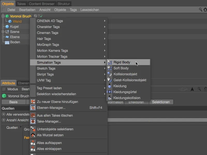
In the corresponding settings dialog, we first ensure that the wall remains intact until the first collision with a bullet by means of Trigger on collision on the Dynamics page.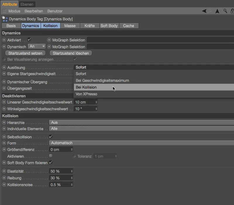
The most important parameter for our fragments can be found on the Collision page. Here, the setting for Individual elements must be set to All so that the pieces broken from the wall retain their dynamic properties.
A low value for elasticity and a high value for friction should work together with the collision objects to keep the fragments on the ground.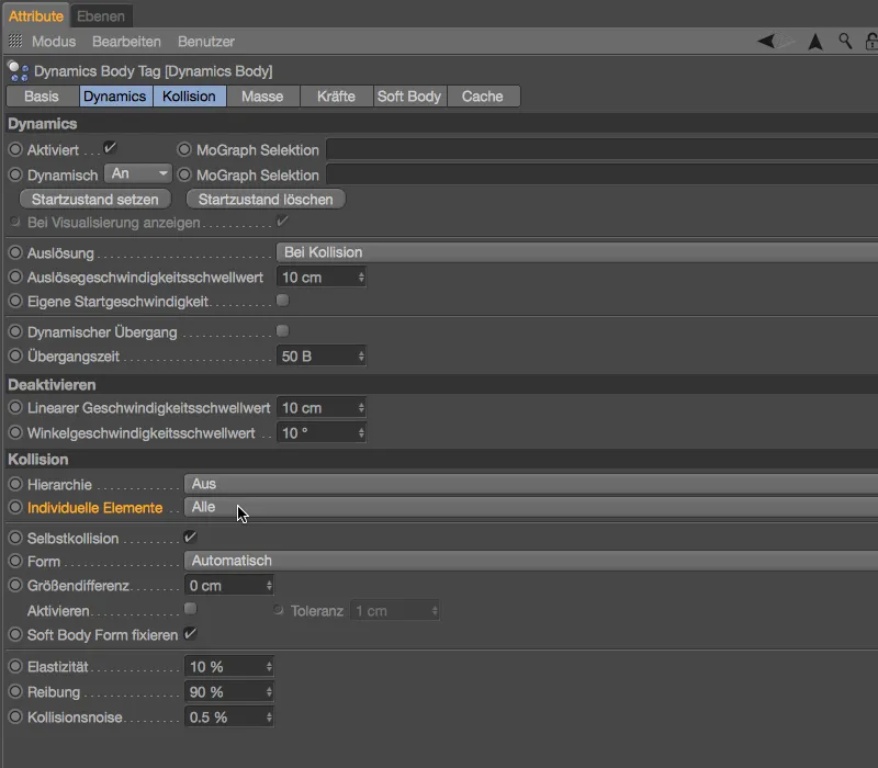
I have provided a simple sphere objectof a suitable size for firing at the wall. Of course, you are completely free to choose the type and number of throwing objects.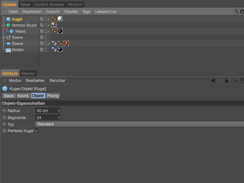
We also assign a Dynamics Body tag as a rigid body to our throwing object via the Tags>Simulation Tags menu in the Object Manageror via the context menu with the right mouse button.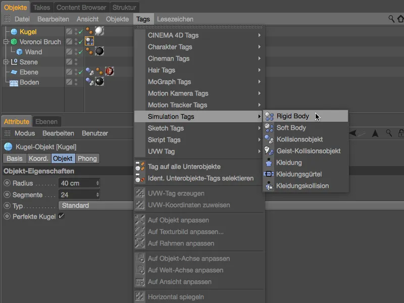
There are now various ways in which we can make the ball hit the wall. An emitter could be used to create a real hail of bullets, but this would be a little exaggerated in our case, as an initial thrust in the positive Z direction is actually quite sufficient.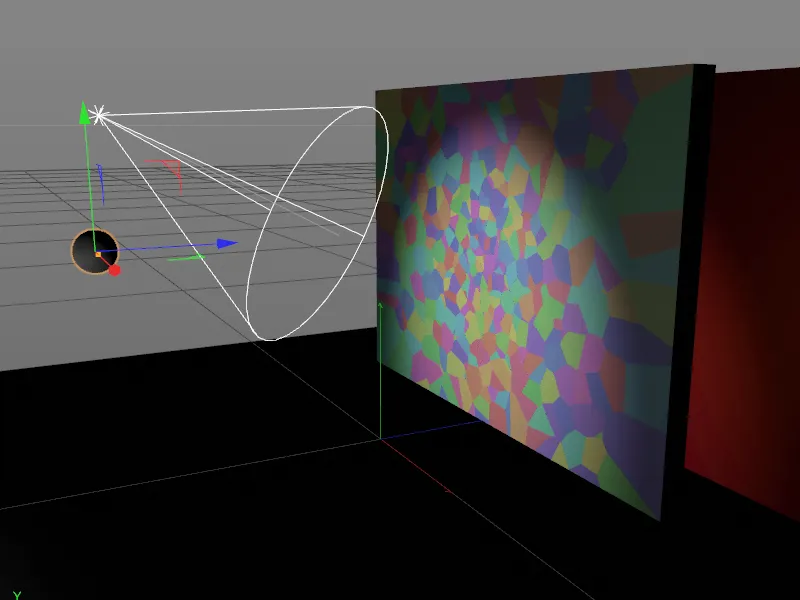
We can easily give the sphere this thrust via the settings dialog of the Dynamics body tag on the Dynamics page. There we activate the option Custom start velocity and set the start velocity in the Z direction to 1000 cm. As the simulation can start with this first ball, we leave the triggering set to Immediately. On the collision page, we assign similar values for elasticity and friction as for the fragments.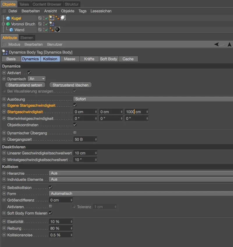
If you haven't already done so, test the animation of the bullet hitting the wall by clicking on the play button. The bullet leaves the first damage with our Voronoi fragments and then rolls away towards the camera.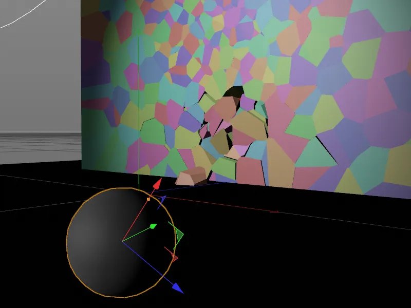
Fine-tuning the wall material
Before we batter the wall with more bullets, let's take a closer look at a rendering from the final camera perspective. The fragments all have a dark gray, concrete-like material, which also continues on the surfaces of the breakage points. However, it would be more realistic if we used a different, lighter-colored material for the inside of the wall in these places. You can already find another, lighter-colored material for the wall in the Material Manager, now we just need to explicitly address the interior surfaces with the material.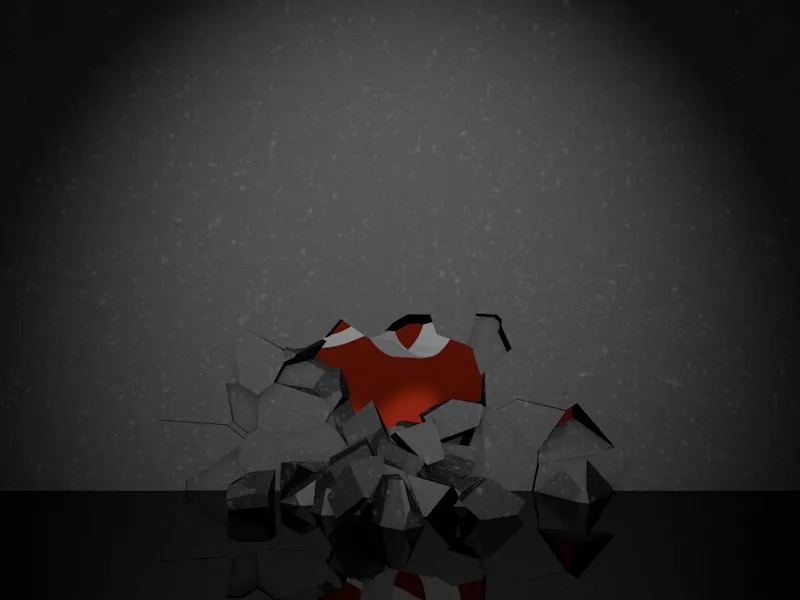
The Voronoi Fracture objectoffers a range of frequently required surfaces, edges and points of the fragments in its settings dialog on the Selections pagefor precisely this purpose. As we want to assign a different material to their inner surfaces, we activate precisely this selection for our fragments.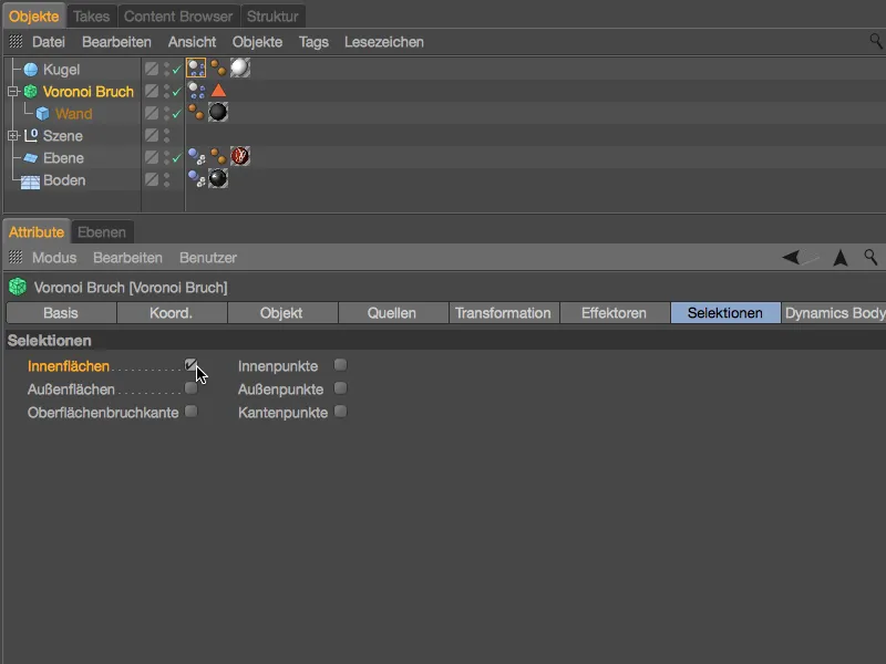
By activating the inner surface selection, the Voronoi fragment objectreceives an automatically generated selection tag in which all inner surfaces of the fragments are stored. It is now easy to assign this selection its own texture.
To do this, assign the lighter wall materialto the wall objectbelow the Voronoi Fracture object by dragging and dropping it from the Material Managerinto the Object Manager. In the settings dialog of the resulting texture tag, drag the selection tag from the Object Managerinto the Selection field of the texture tag.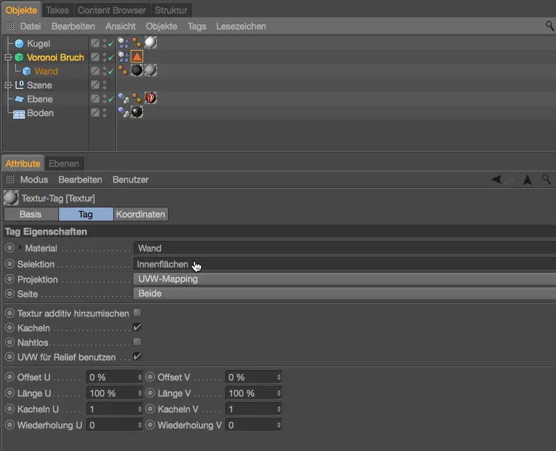
A new rendering shows that the fragments of the wall now have different materials for the outside and inside surfaces as desired.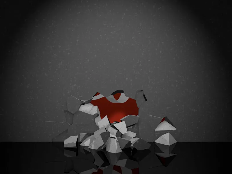
Completing the animation with further spheres
After the first spheres have hit the wall, the PSD logo flashes through a little, but more spheres are needed to fully reveal the logo. For my example, I created two duplicates of the first sphere in the Object Managerby dragging and dropping them while holding down the Ctrl key.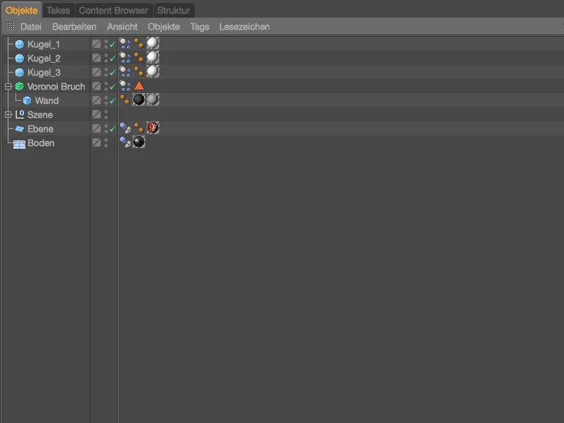
We'll take care of the dynamic properties of the balls in a moment. First, we place the two balls in positions that are favorable for the throws. Once the first ball has hit the lower third of the wall, we move the other two balls up a good distance and offset them slightly in the X direction.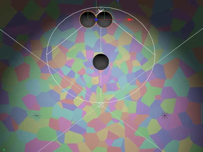
If we now click the play button, all the balls start moving at the same time. It is not for nothing that we have set the triggering to Immediately in the settings dialog of the Dynamics body tag. To fire the balls with a time delay instead, we simply activate the Activated parameter on the Dynamics pagefor balls 2 and 3.
Make sure that the green time slider is set to frame 0, deactivate the Dynamics optionand then set a key for this setting by clicking on the Keyframe buttonin front of the Activated parameter. All other parameters, especially the start speed, have been adopted unchanged from the first ball for the second ball.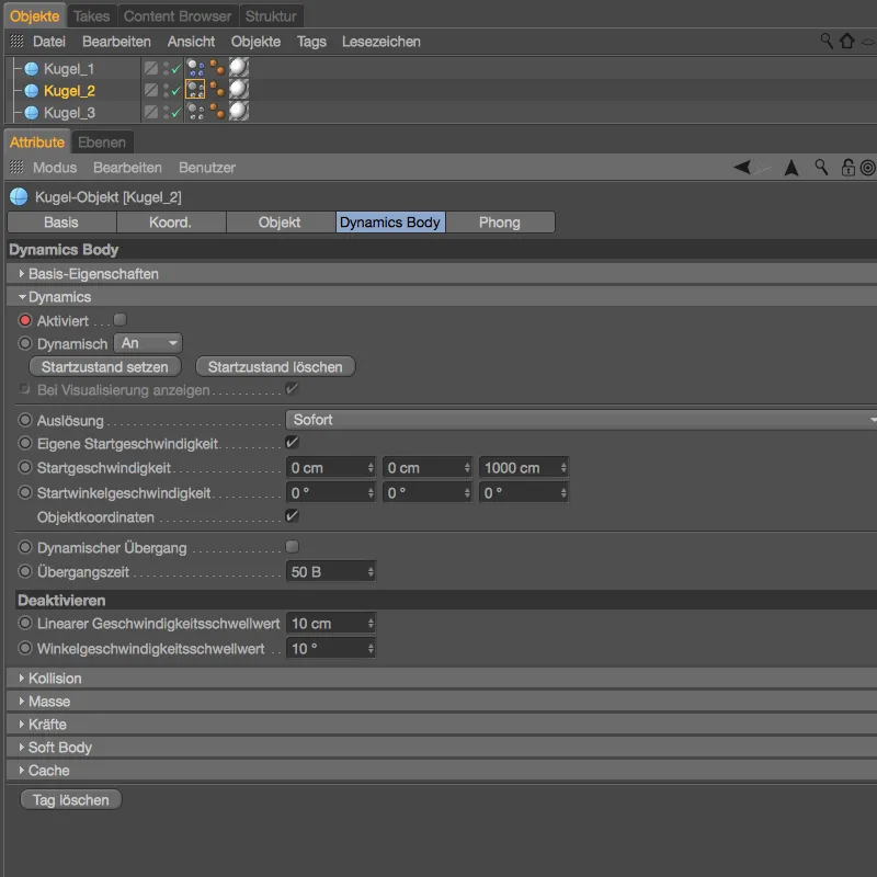
In another test run, I chose image 100 as the time for the start of the second sphere and thus the activation of the Dynamics body tag.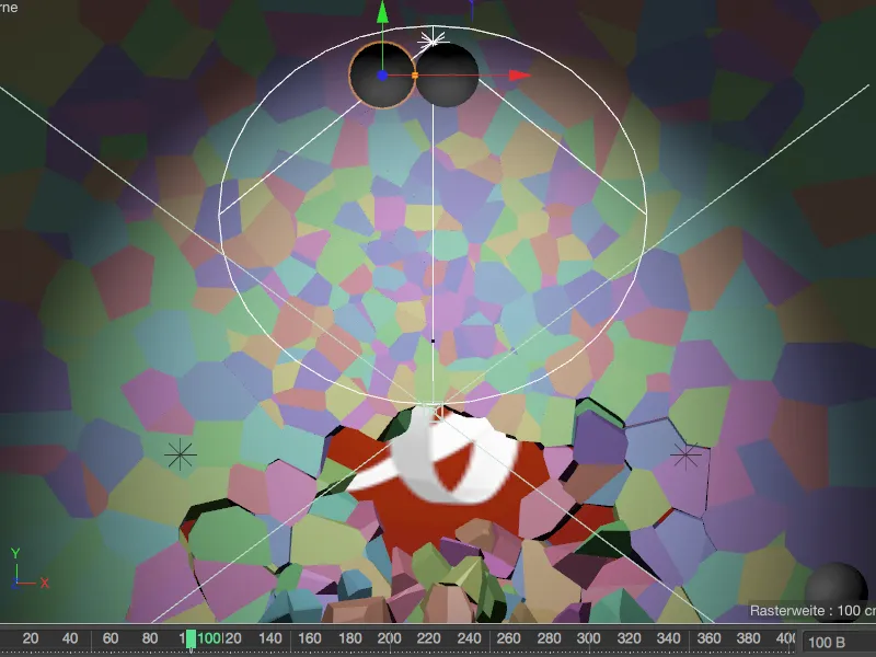
In the settings dialog of the Dynamics Body tag of the second sphere, we only have to check the Enabled parameter and save this setting in a second key by clicking on the Keyframe button.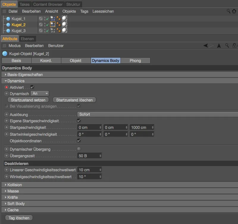
The third sphere follows as soon as the second sphere has also completed its work - in my case at image 180.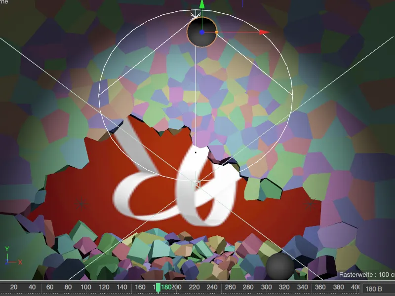
For the third sphere, this means that we need another keyframe at frame 0, which keeps the dynamics deactivated until we check the Enabled box again at frame 180 and save this in a second keyframe.
In my example, I have increased the start speed for the third sphere to 1500 cm so that the sphere reaches its destination, the remaining exposure of the PSD butterfly, safely.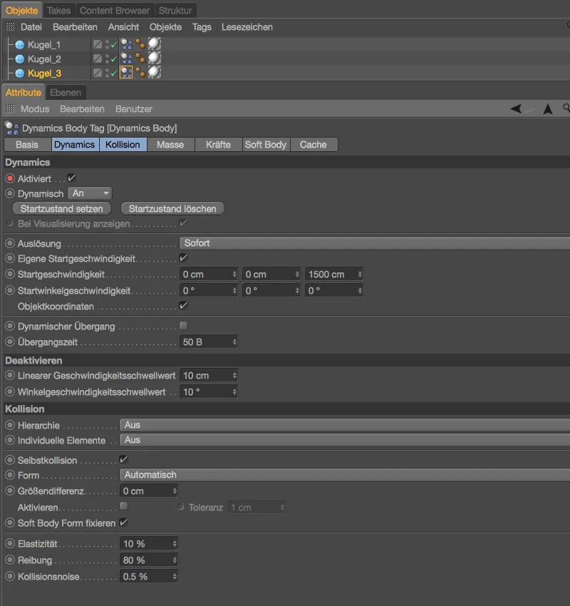
As far as the number, size, position and speed of the balls are concerned, extensive testing is of course a decisive factor. A length of 400 images is stored in the project settings- this should be enough until even the last fragment has come to rest. The animation is now complete.
Baking the simulation
If a simulation - such as the one we have just completed - depends on the MoGraph elements working reproducibly on all computers or even in network rendering, there is no way around baking the simulation.
In the settings dialog of the Dynamics body tag of the Voronoi fragment wall, we go to the cache page. By clicking on the Bake all button, we ensure that not only the fragments but also the spheres are taken into account when baking the simulation.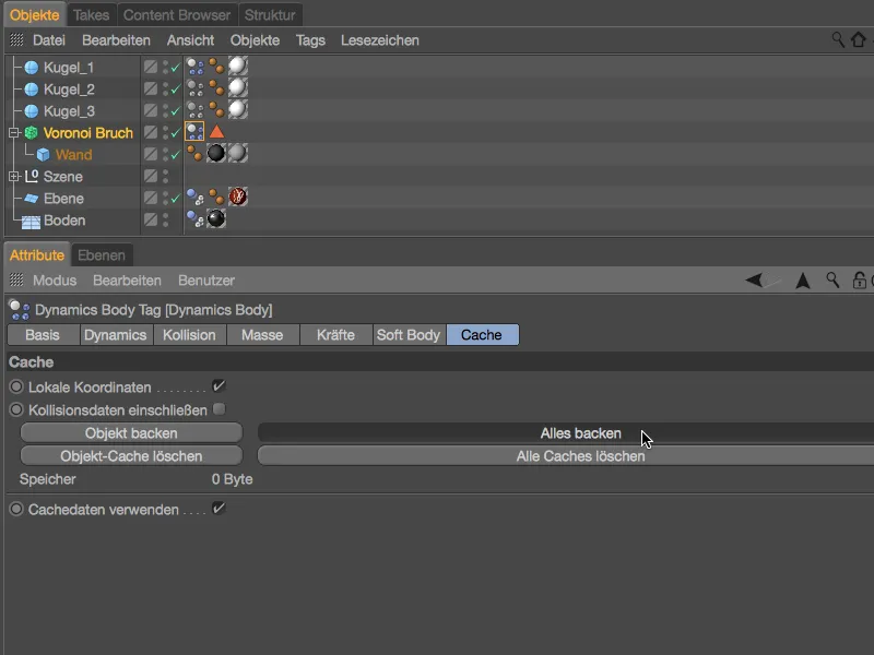
After a short wait ...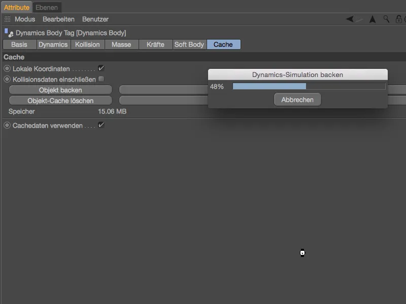
... the simulation is baked reproducibly. We can determine this on the cache sideby the memory used, but also on the Dynamics sideby the inactive parameters. This is ensured by the Use cache data option, which ensures that the simulation runs exclusively via the cache.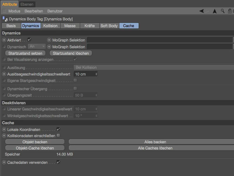
Now we can confidently scroll back and forth on the time ruler with the green time slider, all elements of the MoGraph simulation take part in the constant animation without recalculation.