An astronomical, parallactic mount is the prerequisite for sharp astrophotos with long exposure times: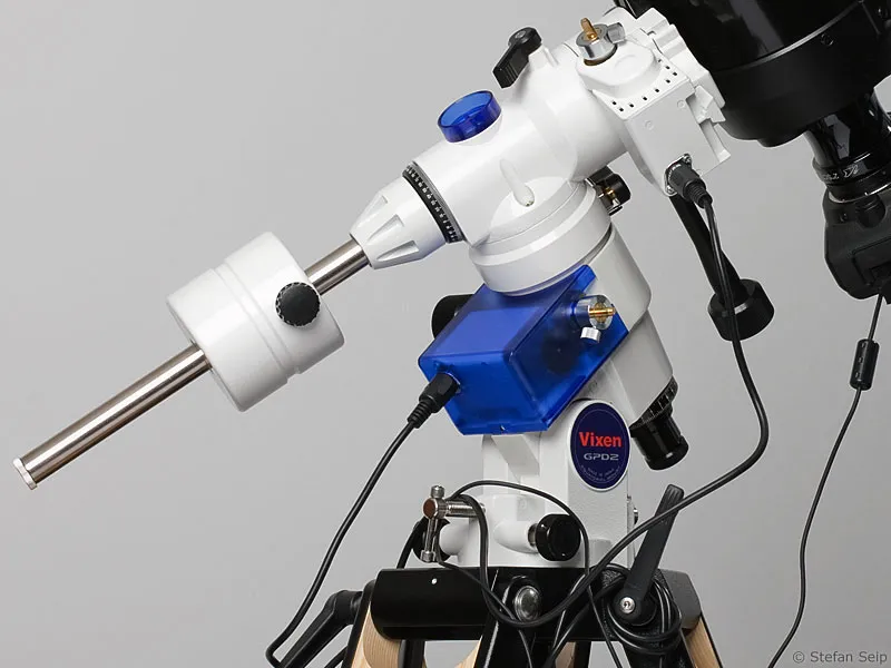
Part 9: Handling an astronomical mount
If a camera is firmly attached to a normal photo tripod, celestial objects will only be imaged sharply if the exposure time does not exceed a maximum value that depends on the focal length, the region of the sky being photographed, the pixel size of the image sensor used and the personal requirements for a "sharp" image.
At a focal length of 3000 millimetres, for example, a blurred image must be expected even at exposure times longer than 1/45 of a second if the camera does not follow the movement of the sky. And even when using a 24-millimeter wide-angle lens, stars are no longer depicted as dots but as tiny lines after an exposure time of 10 seconds.
The reason for this is the rotation of the earth. The sky appears to rotate from east to west above our heads. As a result, not only the sun and moon, but also the planets and stars rise in the east and set in the west. The pivotal point of this movement is the celestial pole (the north celestial pole in the northern hemisphere and the south celestial pole in the southern hemisphere), which is the point in the sky where the Earth's elongated axis touches the "celestial vault" if you imagine the sky as a hemisphere. Inhabitants of the northern hemisphere have an advantage here: very close to the north celestial pole is the easy-to-find Pole Star, also known as the "North Star".
The only way to achieve long exposure times and still capture the stars in a pinpoint image is to follow the rotation of the sky during the exposure time. This requires an astronomical mount in which one axis is aligned parallel to the Earth's axis.
If this axis is then moved at the correct speed during the exposure, "tracked" photos of the sky are produced. This movement is usually carried out by an electric motor. An astronomical mount is also known as an equatorial or parallactic mount.
Components of an equatorial mount. Legend - see overview below: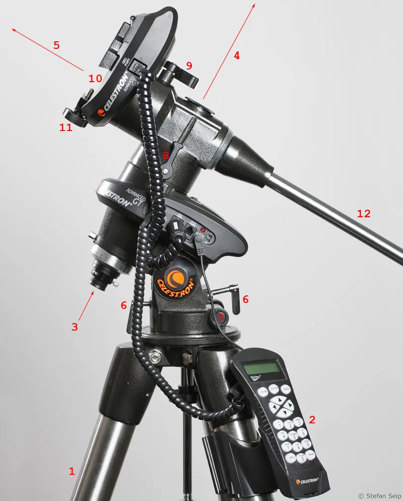
- 1: Tripod (alternative: column tripod)
- 2: Controller (in the case shown: complex computer controller with GoTo function and object database)
- 3: Viewing position of the polar finder scope. It is located inside the hour axis (4), the direction of which is indicated by the arrow orientation.
- 4: Hour axis, which is the only axis that is driven when the mount follows the rotation of the sky. The lower end contains the polar finder scope (3), the upper end is closed with a cover which is removed when the polar finder scope is used.
- 5: Position of the declination axis, which is continued in the counterweight rod (12). There is normally no movement around the declination axis during tracking.
- 6: Pair of screws which, by applying pressure and counter-pressure, allow the angle of inclination (pole height) of the hour axis to be adjusted. It is used to level the mount. Once the mount has been polarized, these screws are no longer adjusted.
- 7: Pair of screws that allow the azimuth (horizontal "viewing direction" of the hour axis) to be adjusted by applying pressure and counter-pressure (the rear screw is difficult to see in the illustration). It is used to level the mount. Once the mount has been leveled, these screws can no longer be adjusted.
- 8: Lever clamping of the hour axis.
- 9: Lever clamp for the declination axis.
- 10: Dovetail guide for holding a dovetail bar to attach a telescope or camera to the mount.
- 11: Screw clamp that secures a dovetail bar inserted into the dovetail guide (10).
- 12: Counterweight rod (without counterweight in the illustration).
Azimuthal mount
Such tracking would not be possible with a photo tripod, even if the fine adjustment were very smooth. It would fail because the image field would rotate around the star being tracked during a longer exposure, as a photo tripod cannot compensate for the rotational movement of the sky. Imagine the constellation Orion: It rises, "lying" on its left side, in the east, rises vertically at its maximum position in the south and sets, lying on its right side, in the west. If you follow this constellation with the photo tripod, the camera would only be moved "up and down" or to the right, but without compensating for the rotational movement.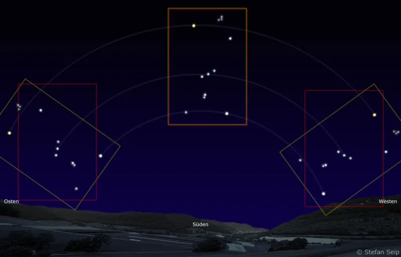
Schematic representation of celestial rotation using the constellation Orion as an example. An azimuthally mounted, tracking camera cannot keep the constellation Orion in the field of view, and the image field rotates over time (red image field frame). If the camera is mounted parallactically, it follows the movement of Orion and at the same time performs a rotational movement so that the captured field of view remains constant (yellow field of view frame).
A mount that only knows up and down movements as well as panning to the right and left is called an "azimuthal" mount and is contrasted with the parallactic mount. A photo tripod is therefore a simple form of azimuthal mount. One of its movable axes is perpendicular to the ground and allows horizontal panning, i.e. adjustment of the azimuth. The other axis runs parallel to the ground and ensures upward and downward movement, i.e. altitude.
An azimuthal mount is not suitable for tracking images of the sky. The mounts of modern large observatories are an exception. There, the optical axis is rotated in a complex process during exposure in order to counteract the rotation of the image field.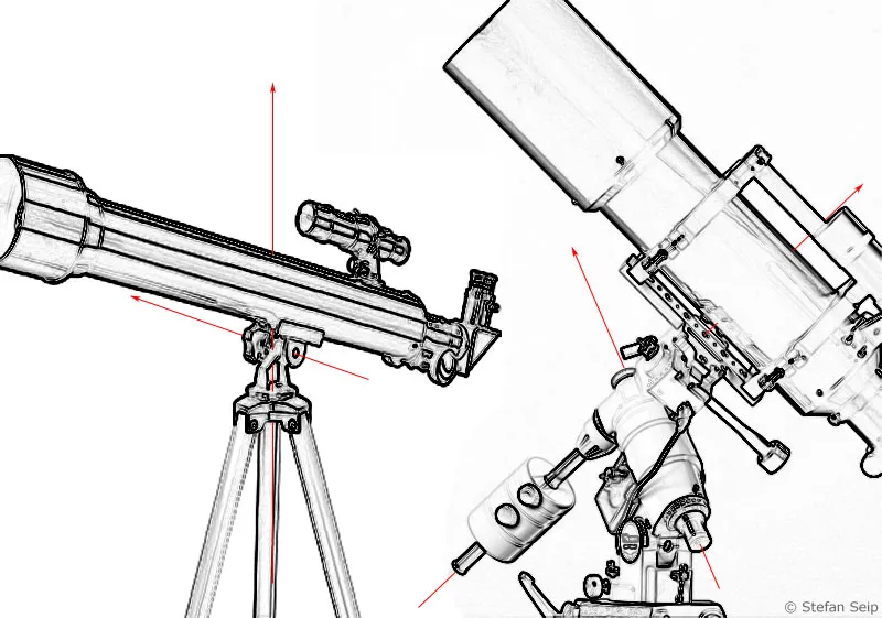
Azimuthal mount (left) and parallactic mount (right). With the azimuthal mount, both axes of movement are perpendicular or horizontal to the ground. It works like a photo tripod. The parallactic mount (right) is characterized by the inclined hour axis (arrow pointing upwards to the left). The "German mount" type requires counterweights on the declination axis (arrow from bottom left to top right).
Parallactic mount
Parallactic mounts are available in various designs. What they all have in common is that one axis is aligned parallel to the earth's axis. This is called the hour axis. There must be a second axis at an angle of 90 degrees to this, the declination axis, in order to be able to align a telescope or camera to any point in the sky.
There are two main types available to amateurs: the so-called "German mount" (named after the country in which its inventor, the German optician and physicist Joseph von Fraunhofer, worked) and the fork mount.
Two equatorial mounts: the fork mount (left) and the "German mount" (right). The red arrows indicate the position of the hour axis.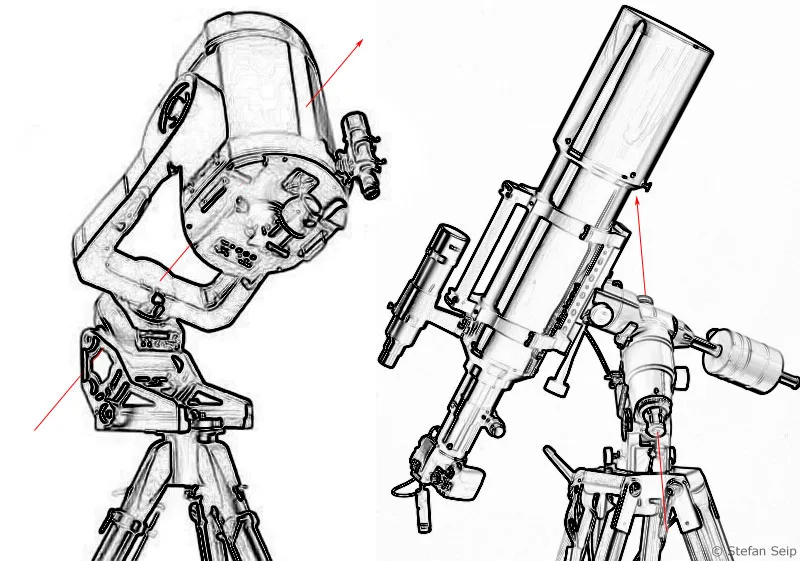
German mount
It consists of an axis cross and is characterized by the fact that the telescope or camera sits on one side of the declination axis, while a counterweight provides balance on the other side. This type is particularly popular and widespread among astrophotographers because the hour axis can be easily aligned with the celestial pole. In addition, the range of German mounts is extensive: all weight and price categories are represented, and the vast majority of them can be purchased individually and not just in conjunction with a telescope. One disadvantage is that when using a telescope, it can strike the tripod or the column when tracking a subject, which makes it necessary to swivel from the west to the east position (or vice versa).
Fork mount
Fork mounts are practically only offered commercially in conjunction with telescopes. As an equatorial design, the entire fork must be tilted so that its hour axis points to the celestial pole, which creates rather unfavorable mechanical conditions. Most fork mounts for the amateur market actually exhibit pronounced oscillation behavior, which is why they are rarely used for astrophotography. In contrast to the German mount, the advantage of the fork mount is that a celestial object can be tracked all night long without the telescope or camera being in danger of hitting an obstacle (tripod/pillar), which means that it is not necessary to swivel around.
Periphery
If you consider the mount to be purely axial mechanics, further components are required to turn it into a functional unit for astrophotography:
- 1. tripod/pillar
A tripod has advantages in mobile use because it can be set up practically anywhere. A column offers more freedom of movement for a telescope, but only stands securely on a level surface. Whatever the decision, a high degree of stability should be ensured. Ultimately, the weakest link in the whole chain will limit the stability and therefore also the maximum tracking accuracy.
- 2. motors
Some mounts are supplied with motors already installed, others have to be purchased separately. For short exposure times, the motorized drive of the hour axis is basically sufficient, i.e. there is no need for a second motor for the declination axis. For longer exposure times, corrective movements of the declination axis may also be necessary, so that two motors - one for each axis - are recommended. Most mounts work with stepper motors that run with microsteps and move the mount axes via a worm and a gear rim. Another solution is servo motors.
- 3. control unit
Every mount requires a controller. If it is not included in the scope of delivery, it must be purchased separately. The task of the controller is to supply the motors with voltage and drive impulses. In addition, it provides the more or less fast and fine motorized movement of the mount in all directions via four buttons.
In addition to these fundamental functions, some controllers offer further features:
- Changing the tracking speed (in addition to sidereal, i.e. to the stars, optionally also for the sun and moon)
- Autoguider connection: a socket for regulating the movement of the mount using a special digital camera called an autoguider, should this be necessary. Anyone working with long focal lengths and long exposure times will sooner or later want to leave the "tracking control" to an autoguider and attach importance to equipping the controller with an autoguider connection.
- GoTo function: In conjunction with fast motors, a GoTo control enables automatic positioning of the mount on a celestial object of your choice. The GoTo function does not play a decisive role for astrophotographers, so if in doubt, a limited budget should be invested in a more stable mount.
Manual control box of a telescope mount: Two buttons each allow motorized adjustment of the hour axis (1) and the declination axis (2) in order to align the telescope precisely to a celestial object. A slide switch on the side (3) can be used to switch the control on and off and to select operation in the northern or southern hemisphere of the earth. Switch 4 is used to set the speed of movement of the motors when using buttons 1 and 2.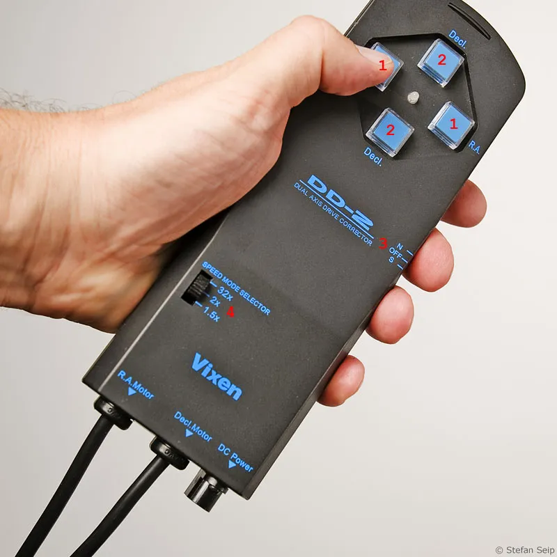
- 4. polar finder scope
This is a mini telescope that is screwed into the hollow hour axis of the mount and enables quick and convenient polar alignment (see below).
Simulated view through a polar finder scope. The blue sky corresponds to the view in advanced twilight. The elements visible in the eyepiece are illuminated by a red LED and can therefore be recognized even against a black sky. The nominal position of the polar star (Polaris), which can be seen at the corresponding position in the image, is clearly visible. The deviation of the pole star from the true celestial pole (center of the field of view) is automatically taken into account. The constellations shown only indicate the directions and are not visible in the polar finder scope.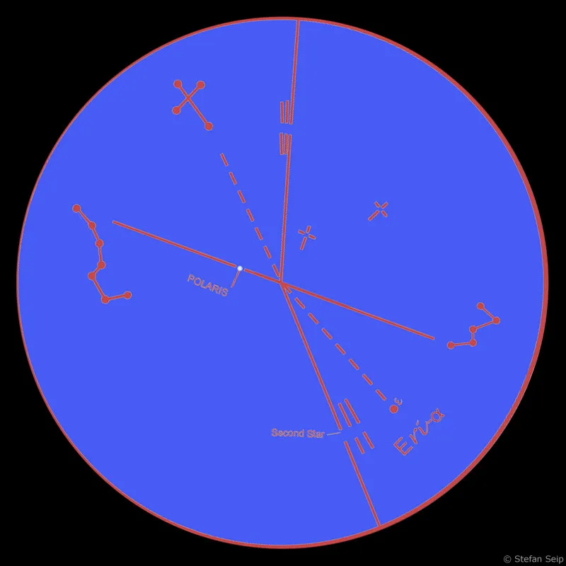
- 5. power supply
Mounts are usually operated with 12 volt direct current. A battery pack or an appropriate rechargeable battery must therefore be procured for mobile use.
- 6. mounting rail
To attach a telescope or camera to a mount, additional small parts are usually required. Many mounts have a dovetail guide as a connection platform. A suitable dovetail bar must then be provided on the telescope or camera side. If a camera is to be attached, a stable ball head is a good addition.
Installation
An equatorial mount must be set up so that the hour axis points to the celestial pole (i.e. close to the pole star). This process is known as "polar alignment".
The easiest way to achieve polar alignment is with a polar finder scope. The prerequisite for this is that the celestial pole and the North Star can be seen from the observation point and are not obscured by a tree or a house. The polar finder telescope looks through the hollow hour axis and shows a mark representing the nominal position of the pole star when looking through it.
The deviation of the pole star from the true celestial pole, which is currently around one and a half full moon diameters, is also taken into account. Depending on the design of the mount and the polar finder scope, only the current position of Polaris relative to the pole needs to be set, as it orbits around the pole once a day.
Then only the inclination (pole height) and the viewing direction of the polar axis (azimuth) need to be adjusted until the pole star can be seen in the intended position in the polar finder scope. The inclination of the polar axis corresponds to the latitude of the observation location, i.e. about 50 degrees for Frankfurt/M. A good mount allows the polar axis inclination to be finely adjusted for any corrections. The viewing direction is done by a likewise sensitive azimuth adjustment.
In order to adjust the "viewing direction" of the hour axis, i.e. the azimuth, two hand screws must be moved, which act by pressure and counter-pressure on a spike on the tripod plate and allow the mount to be aligned horizontally in the course of polar alignment.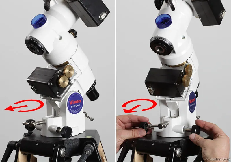
The angle of inclination of the hour axis, i.e. the adjustment of the pole height, is also carried out by two hand screws which work with pressure and counter-pressure. This angle of inclination corresponds to the latitude of the observation site and only needs to be adjusted once during polar alignment.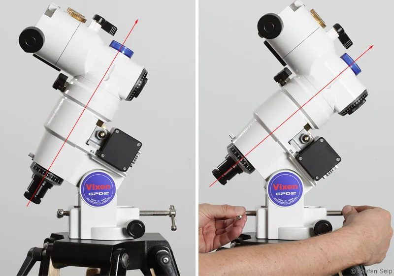
Even with longer focal lengths and longer exposure times, the polar alignment is accurate enough using an adjusted polar finder scope. For short exposure times with shorter focal lengths, it is even sufficient to simply position Polaris in the center of the field of view of the polar finder scope.
The "Scheiner" method is only recommended for polar alignment if high demands are placed on the precision of polar alignment, as may be necessary for very long exposure times, long focal lengths, stationary observatories or the best possible positioning accuracy of GoTo mounts. It assumes that a telescope and a reticle eyepiece are available. A detailed description of this time-consuming procedure can be found at
http://www.baader-planetarium.de/montierungen/download/scheiner-klassic.pdf
Once the mount has been aligned, it is loaded, i.e. the counterweight, telescope and/or camera are attached. The next step is to balance the hour and declination axes. Ideally, the mount will then remain in its position without the axes being jammed, regardless of the point in the sky to which it is aligned.
For this purpose, a mounted telescope is aligned so that it points exactly south (or north) and is directed towards the horizon, i.e. it is in a horizontal position. First, the counterweight is moved axially on the counterweight rod until the mount remains in its position even without clamping the hour axis.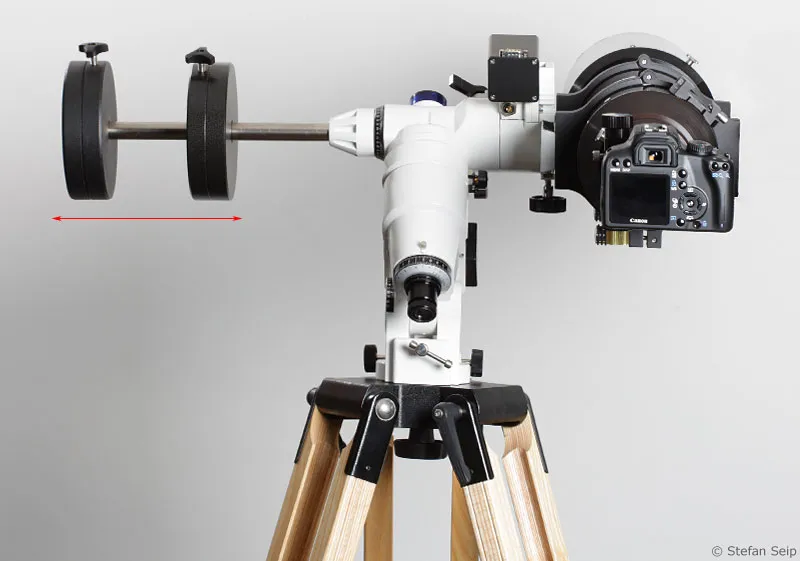
View of the mount from the south. The telescope with camera (right) was aligned to a point on the horizon in the north. By moving the counterweights (left) axially, a balance is established so that the telescope remains in this position even if the hour axis is not clamped.
The hour axis clamp is then tightened and the telescope is moved along its optical axis in its tube clamps (or by longitudinal displacement of the prism rail in its holder) until the declination axis is also in equilibrium.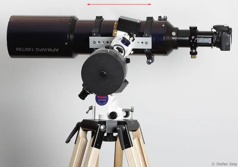
View of the mount from the east. The telescope with camera (rear) was aligned to a point on the horizon in the south. By moving the prism rail (aluminum-colored bar with holes) in the dovetail guide or by moving the telescope in its tube clamps along the double arrow marked in red, equilibrium is again achieved. The telescope then remains in this position even if the clamping of the declination axis is released.
It is not always possible to achieve this ideal position. But then you should at least try to get as close to it as possible. The aim of balancing is to ensure that the motors have to do as little work as possible when moving the mount. If there is a strong imbalance, it is also to be expected that the motorized tracking will no longer work with the required precision.
After this step, you will have a functional system for tracking the camera along the path of the stars without the Earth's rotation causing streaky images of the stars during long exposures.
To do this, connect the control unit of the mount and supply it with power. Make sure that the tracking speed is set to "sidereal" or "star" if you are photographing celestial objects other than the moon and sun. If the controller also allows the mount to be operated in the southern hemisphere of the earth, "north" must be set, otherwise the hour axis will rotate in the wrong direction. Now loosen the clamps on the hour and declination axes and point your telescope and/or camera at the desired region of the sky, then tighten both clamps again with gentle pressure. Wait a few seconds before starting the first exposure to give the drive worm time to engage fully with the teeth of the gear rim.
The next two episodes of the tutorial series "Astro and sky photography" will deal with the topics "Long exposures with a tracking camera" and "Tracking control during a long exposure".
Transportation
When transporting an astronomical mount, the counterweights should be removed and the clamps on the hour and declination axes should be loosened. This protects the mechanics in the event of vibrations.
Examples of mounts suitable for photography
When it comes to reducing luggage dimensions, the "AstroTrac 320x" mount is hard to beat. This is an attachment for photo tripods, the picture shows the aluminum-colored part. Optionally, this mount can even be equipped with a polar finder scope (top left), but a tripod and tripod head are required.
It is suitable for tracking cameras with lenses up to a focal length of about 300 mm and at best for very small and light telescopes. A battery pack powers the motor for tracking. When folded, the mount is as big as a warning triangle in a car, but its price is unfortunately quite high (from 625 euros).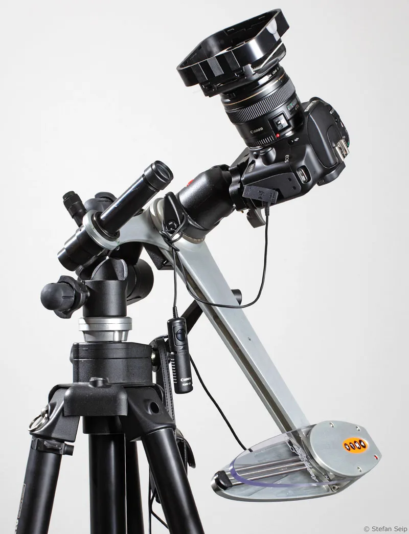
The "Skywatcher EQ-3" represents the absolute lower limit for tracking images with classic telescope mounts if it is equipped with motors, as can be seen in the next image. At best, the smallest telescopes can be considered as a "payload", rather a camera with photo lenses and not too long focal lengths. For shots with moderate focal lengths and a few minutes of exposure time, however, it is definitely a suitable platform, which is available including tripod, motors and control unit for around 230 euros.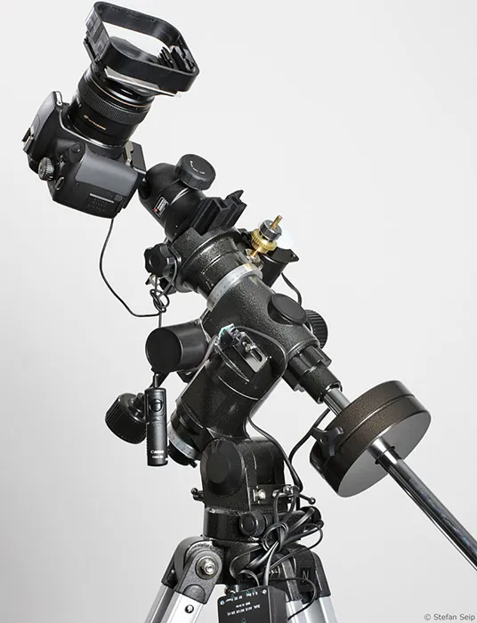
The "Celestron Advanced GT" with GoTo control is significantly more stable. It also supports telescopes of medium size and focal length. However, it must not be overloaded for photographic requirements in the course of long exposures, as the precision of the tracking is not sufficient for very long focal lengths. As a complete package with tripod, polar finder scope and GoTo control, this mount costs approx. 750 euros.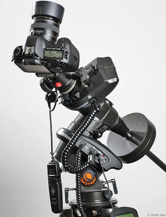
The "Vixen GPD2" is a real "workhorse" and is suitable for photography in every respect and worth a recommendation. It is not cheap and even the motors are missing in the basic version, but it carries a payload of around 8 kg (without counterweight) without complaint and its mechanical precision meets all the requirements for photographic use. The "naked" axis cross without tripod, control, motors, but with a very precise, illuminated polar finder scope costs 800 euros. A complete configuration with fast motors, GoTo control and wooden tripod can add up to 1800 euros.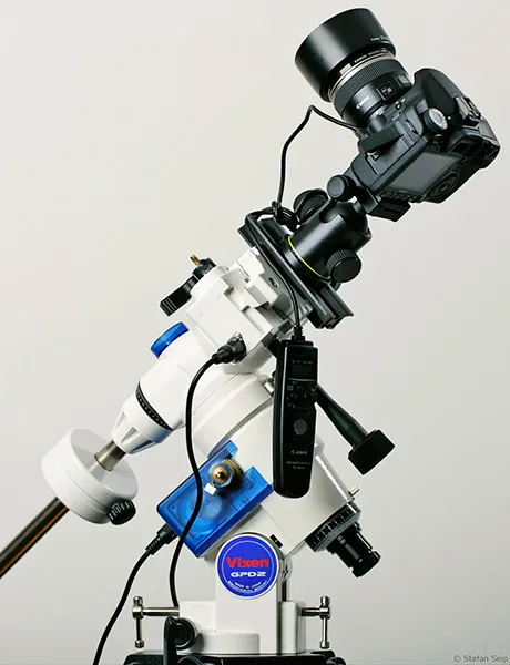
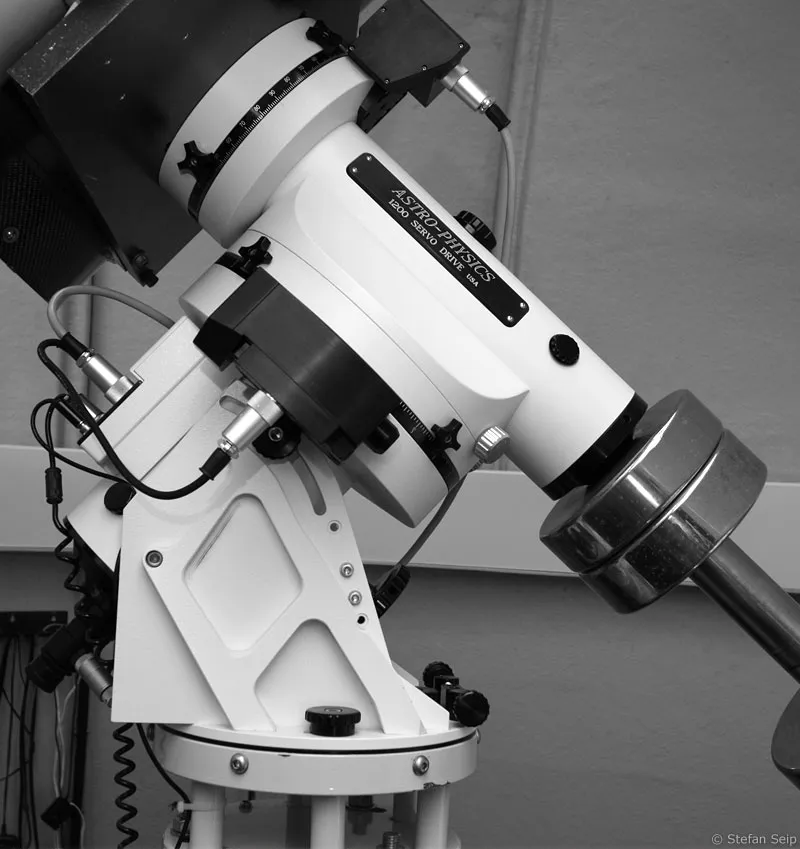
The "1200 GTO" from Astro-Physics is an extremely heavy, but still reasonably transportable mount, as the declination block can be separated from the polar altitude unit and transported separately. Both together weigh over 50 kilograms without accessories. This mount is in good hands in a stationary observatory, its load capacity is almost 65 kilograms without the counterweights! For the mount without accessories, but with GoTo control, a five-digit euro amount is to be estimated.