As with every release, Cinema 4D R17 also offers numerous new features and improvements that make everyday 3D work easier. Hardly any program area remains untouched.
Color picker
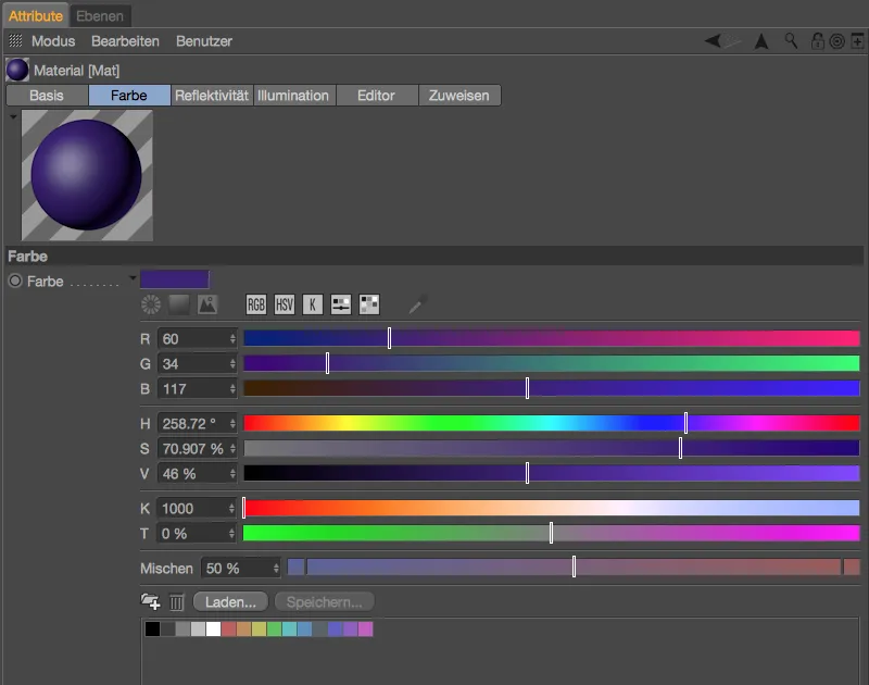
When selecting a color, we always encounter the color picker, regardless of whether we are defining a new material or coloring an element in the editor or a layer. The color picker has been greatly expanded and redesigned in Release 17. By expanding the color chip on the color parameter, small icons are available to help us set the desired color: Color circles, color spectra, image sources, RGB, HSV, color temperature slider and blend slider. The reuse of colors was also previously done via a color memory, but what is new is that we can create groups and load and save presets.
The presets for the color picker can be found in the Units section of the program presets. So if, for example, you prefer RGB mode in the color picker instead of HSV mode, which is activated by default, you can save this setting and a few other adjustments in the Color picker>Preset set section.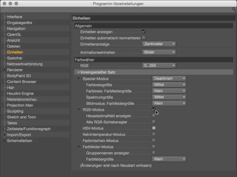
Let us now turn to the new functions of the color selector. Color circles are predestined for the definition of color series; Adobe's Kuler certainly comes to mind here. After selecting the color wheel modevia the corresponding icon, we have the option of choosing between the free definition with any number of color handles or the tried and tested color harmonies (monochromatic, complementary, analog, partially complementary, tetrad, equiangular) as a color wheel.
You can create additional color handles using the + symbol, while you can delete color handles using the - symbol. You can lock the angle between the color handles, which allows you to change the color wheel as a whole, by clicking on the lock symbol.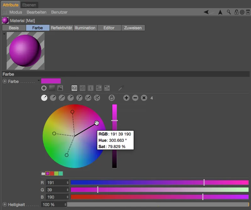
By clicking with the right mouse button on the color wheel, you can access the associated context menu and choose between an accurate and an artistic color combination, swap the color wheel and slider function and also set the size of the color wheel.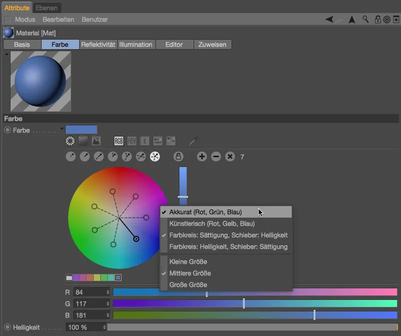
The second symbol in the color selector hides the familiar square spectrum display. On the far right of the row of icons you will find an eyedropper to pick up color from any area of the screen.
A completely new feature in Release 17 is the option to load an image source into the color picker in order to extract colors from it. After loading the image using the button to the right of the link, the first round color picker is already in the middle of the view; you can add further pickers by clicking on them while holding down the Ctrl key.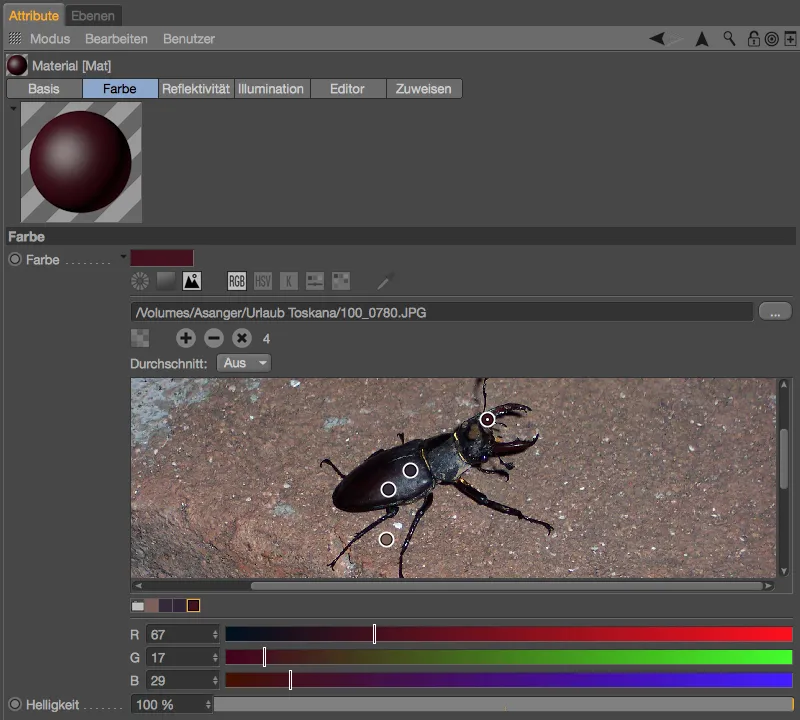
Mesh check
The first new feature in the modeling area concerns the mesh check, which you can access via the modeling settings in the Mode menu of the Attribute Manager. There is now an additional option to search for edge points.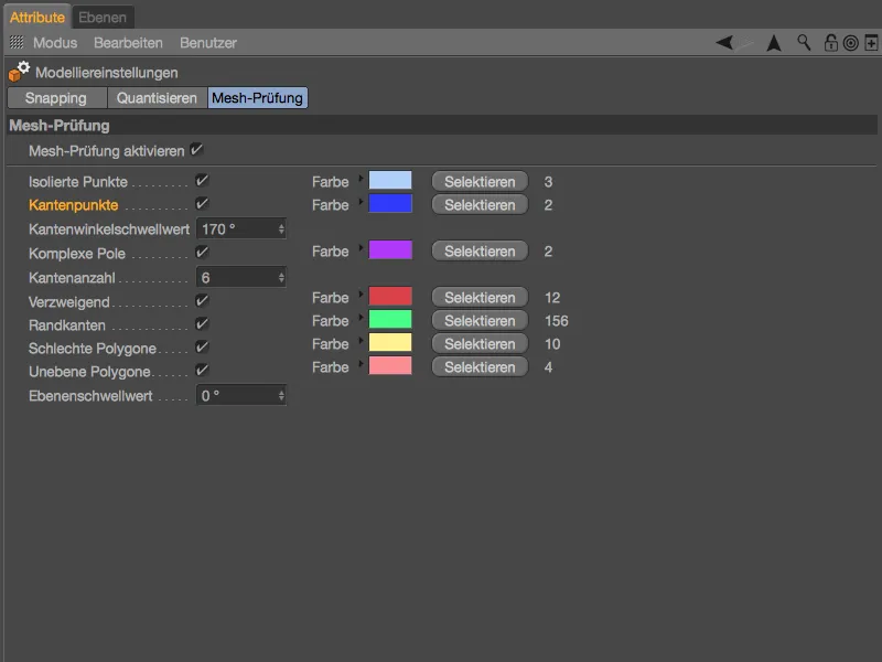
Edge points occur with N-gons, i.e. they lie on an edge without defining a (necessary) corner point themselves. The mesh check can be used to search for these potential interferers and delete them if necessary.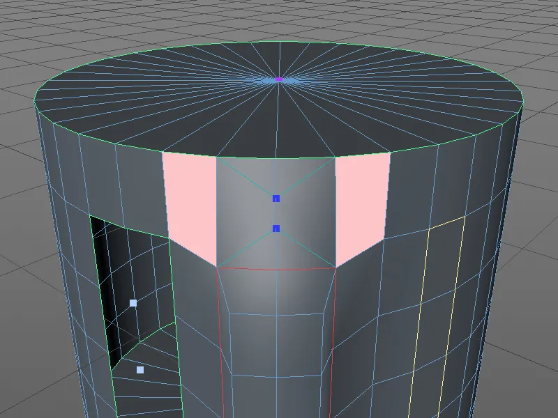
Metaballs
The second innovation in the modeling area, which includes improvements in shading and offers two additional envelope shapes, came rather unexpectedly. For our example, I took an icosahedron as a platonic body from the palette of basic objects, converted it into a polygon object and added an extrusion to its polygons.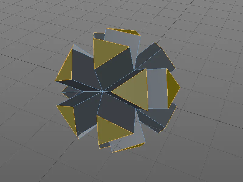
The polygon object is subordinate to the metaball object. A 60% adjusted envelope and a subdivision of 5 cm are stored in the settings dialog of the metaball object. While in the versions prior to R17 only the sphere was available as an envelope shape, we now have two other shapes available in the metaball tag assigned to the polygon object.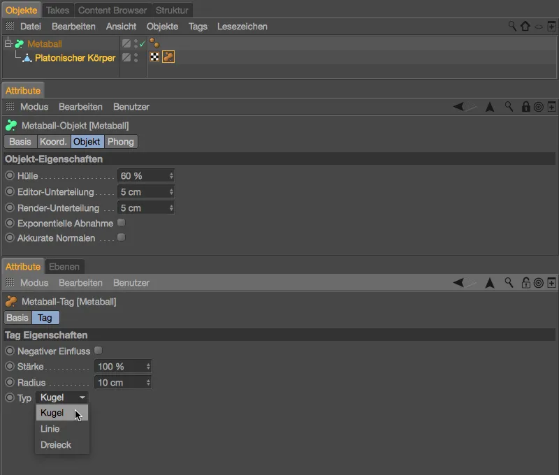
Due to the relatively small radius, it is easy to see that the metaball spheressit on the corner points of the polygon object. The edges or faces of the polygon object are not taken into account.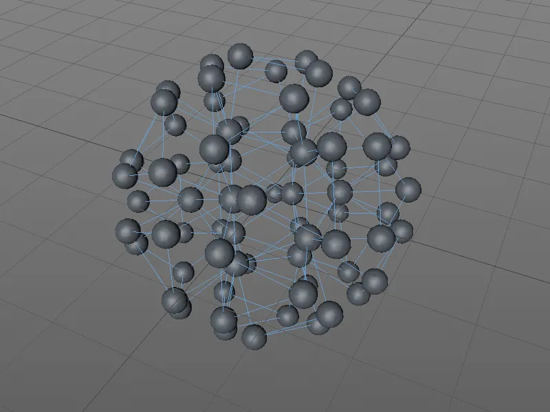
If we now set the type to Line, we can also use the polygon edges in the metaball object. For better visualization, I have set an 80% envelope in the metaball objectwith a subdivision of 2 cm and a slightly smaller radius of 8 cm in the metaball tag.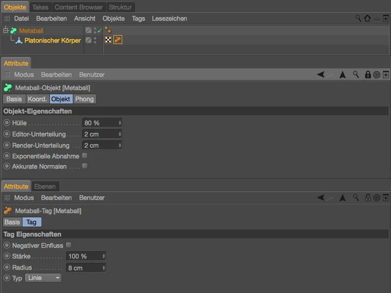
Instead of being generated exclusively from the polygon's corner points, the metaball objectis now generated from all edges. Unfortunately, the shading of the surface is very coarse. Of course, we can quickly correct this by increasing the subdivision, ...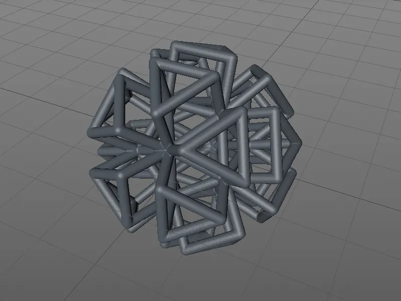
... but in Release 17 we also have another option to ensure better smoothing. In the settings dialog of the metaball object, there is the option Accurate normals, which uses internally calculated, custom vertex normals.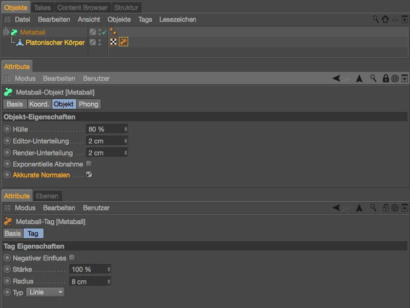
With this special smoothing, the surface of the metaball objectlooks much better.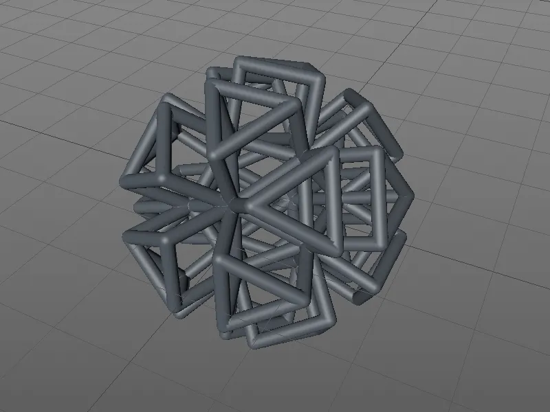
The third envelope shape, the triangle type, is still missing. This means that the surfaces of the polygon object are also included here in the form of triangles for the metaball object. For better displayability in our example, I have reduced the envelope to 30 %, set the subdivision to 1 cm and increased the radius in the metaball tag to 25 cm.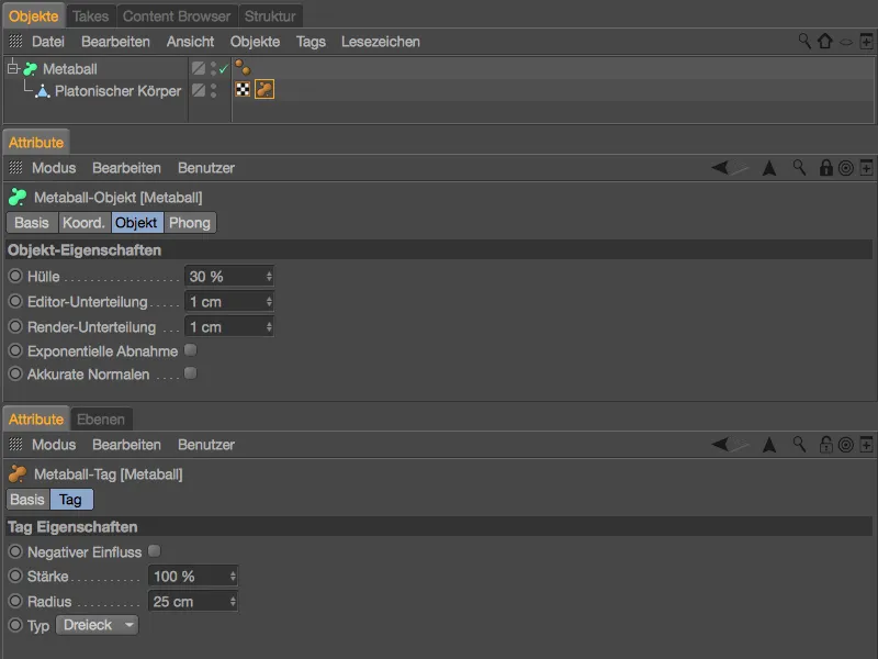
As we wanted, the metaball objectis formed from the triangles of the polygon object. Even if the external appearance gives a different impression, it should of course always be noted that there is geometry inside the metaball objectin the form of the other part of the shell.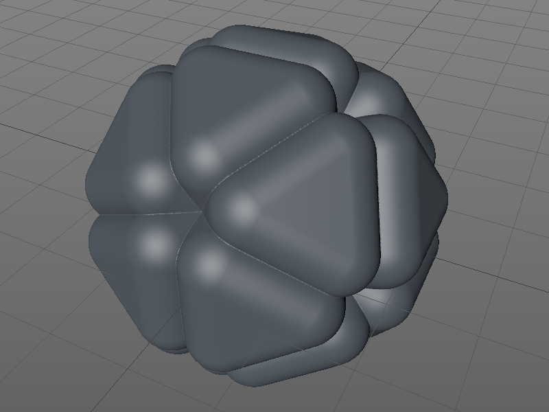
Sculpting (BodyPaint 3D and Studio only)
As in every new release of Cinema 4D, the Sculpting area has also been given some new functions.
For example, if you split the shaping of a character's poses into different sculpting layers, you can use a simple command in the Sculpting menu to automatically convert them into pose morph poses.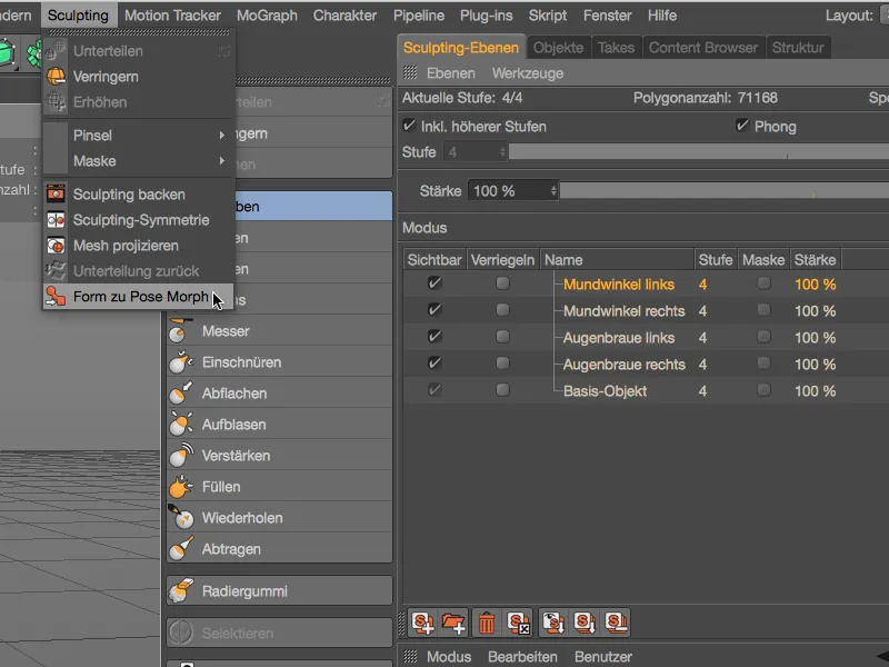
When sculpting with the Sculpting brushes, the new Edge Detection option helps to reduce the brush effect on or in front of the edges.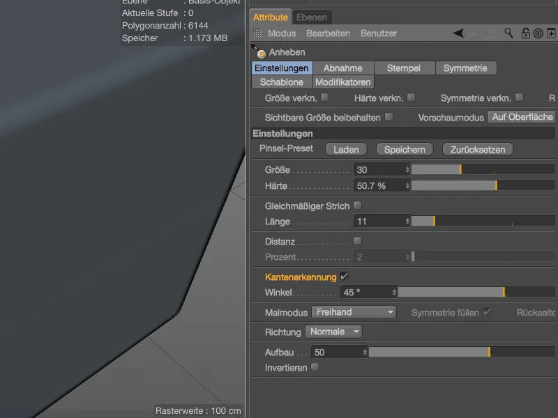
Let's take a look at this in an example with a simple polygon cube. If the Edge detection option is deactivated, the sculpting brushdoes not take the edge into account and has an unrestricted effect on all areas of the cube.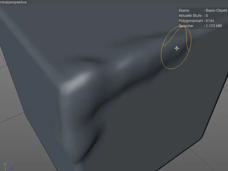
If the edge detection option is activated, it is easy to stay below the edge with the sculpting brushand to end the shaping specifically at the edge.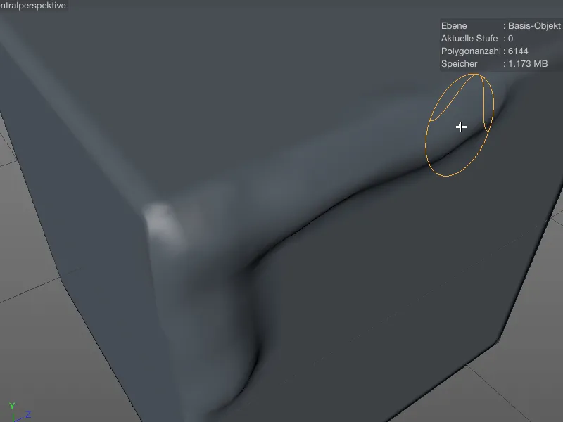
Whereas before version R17, objects to be mirrored using the sculpting symmetry had to be symmetrical in order to achieve satisfactory results, the Find next point option allows the mirroring function to work much more tolerantly.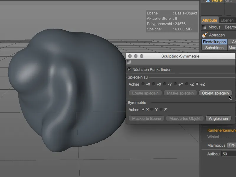
Points that are very close to the mirroring axis are set to the axis. The option is deactivated by default, but it is always worth a try if the results are unsatisfactory.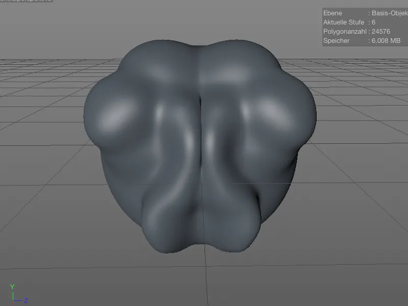
For all sculpting brushes, with the exception of the bevel brush, the Back option allows you to shape the back of the surface. The brush effect or orientation is not reversed, except for the Abrade and Fill brushes.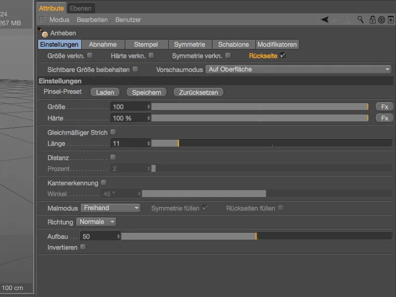
In the editor, you can see from the blue-colored brush preview that you are working on the back of the surface with the Sculpting brush.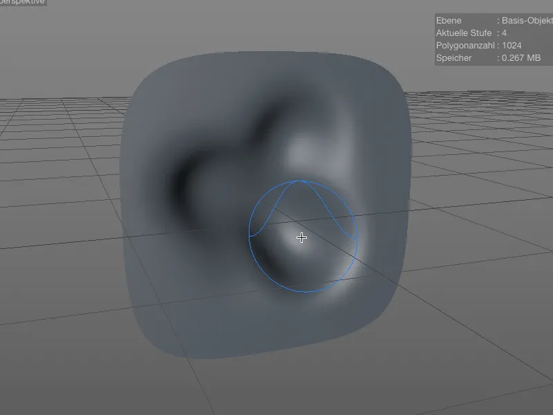
Timeline and keyframes
There are no spectacular new features in the animation area, but there are some interesting improvements to details. For example, a marker in the timeline can now cover a period of time rather than just a point in time. Simply enter the desired length in the marker settings dialog.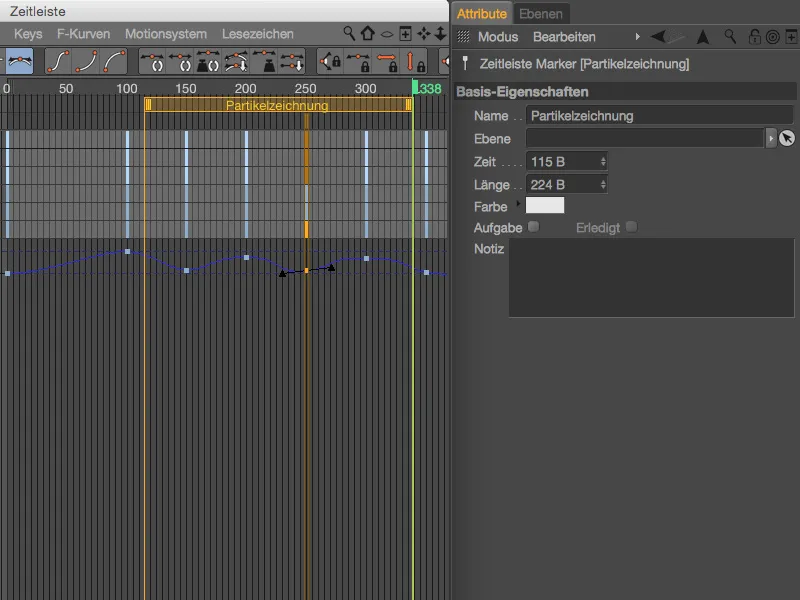
When working with keyframes in the timeline, the Shift keynow also has an effect. When moving in a vertical direction, you can therefore move time-neutrally, ...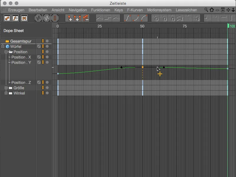
... when moving horizontally, you can change the value neutrally while holding down the Shift key.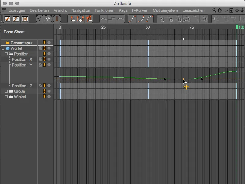
The improvements to the keyframe properties go into even greater detail. In addition to some new tangent functions, Release 17 also offers key presets for the most common key behaviors. But first things first:
By activating the Weighted tangent option, the length of the tangents changes according to the proximity to the neighboring keys when the key is moved. We must first enable this automatic process using the Auto tangent option. 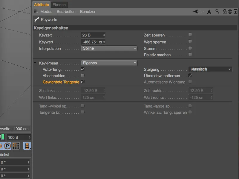
So if we move the keyframe in the direction of the left keyframe neighbor during editing, the left tangent on our keyframe is shortened and vice versa.
When creating and modifying keyframes, the soft interpolation quickly results in overshoots that exceed the maximum value actually set in the curve. You can switch off this usually undesirable property in advance using the Remove overshoot option or optimize it afterwards.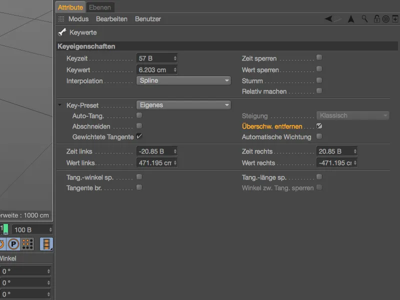
In the example shown, there is a very clear overshoot on both sides of the middle keyframe. The Remove overs hoot option was of course not activated.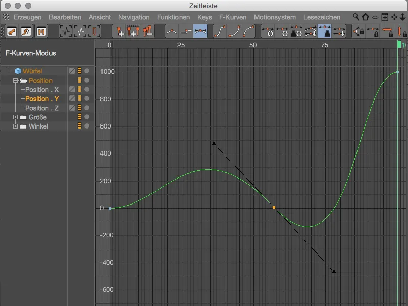
Activating the Remove overshoot option is sufficient to adjust the curve so that the overshoot is removed and no longer occurs for this keyframe.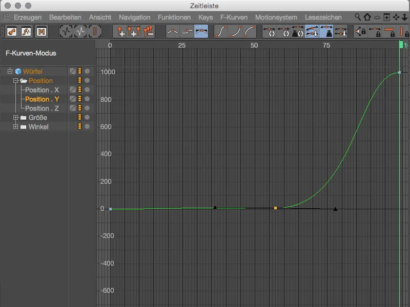
Also new in Release 17 is the option of defining the slope at the tangents. Before version 17, the slope was adjusted depending on the proximity to the neighboring keyframes, which corresponds to the Classic setting. However, if we set the value to Constant slope...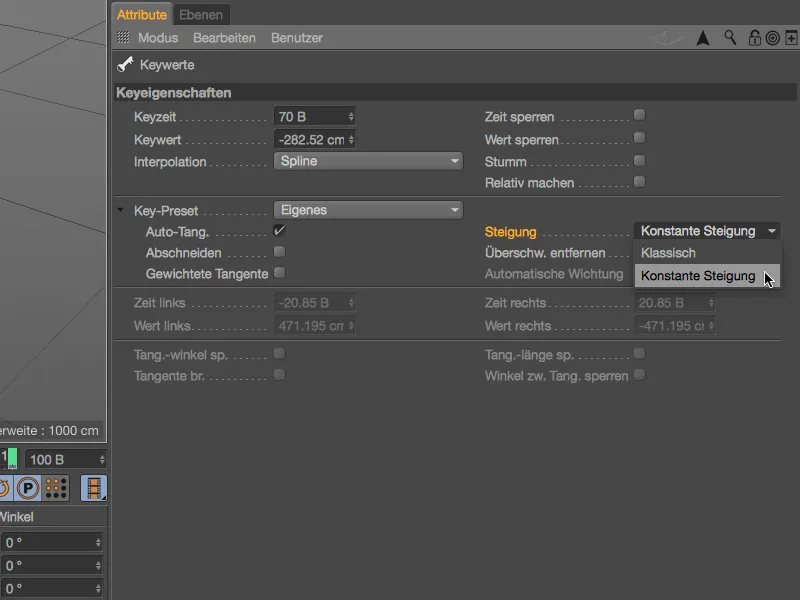
... the slope in the tangents always remains constant when the keyframe is moved within its range.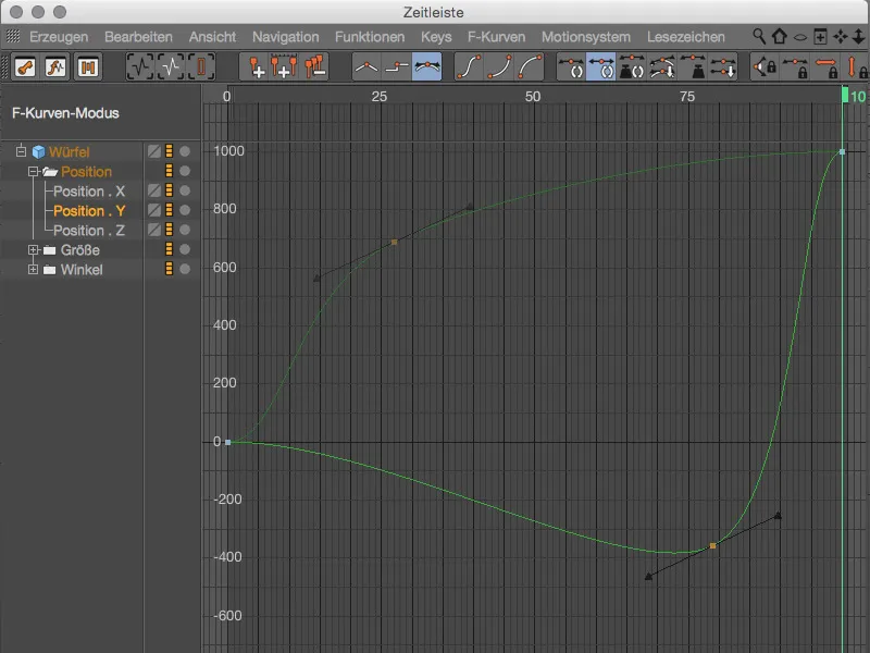
By activating the last new key property Automatic weighting, the tangents of the key are assigned an initial weighting. The tangents can then only be rotated to change the gradient, ...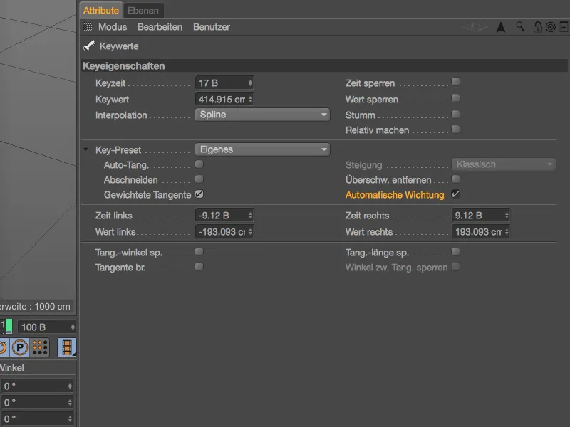
... otherwise the slope of the tangents remains untouched when the keyframe is moved.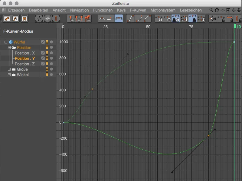
If you are looking for a few standard recipes among the many possible combinations, you are sure to find them in the key presets. Auto-Key: Classic corresponds to the behavior before R17, the next level Auto-Key: No Overshoot contains overshoot avoidance, while Auto-Key: Weighted uses all the advantages of weighted tangents.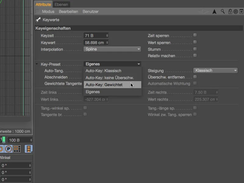
Motion Tracker (Studio only)
With the so-called Motion Tracker Graph, Cinema 4D Release 17 offers a visual aid for assessing the quality of the tracking. If the 3D reconstruction does not work as desired for reasons that are difficult to understand, the graph from the Motion Tracker menu can help you find the cause.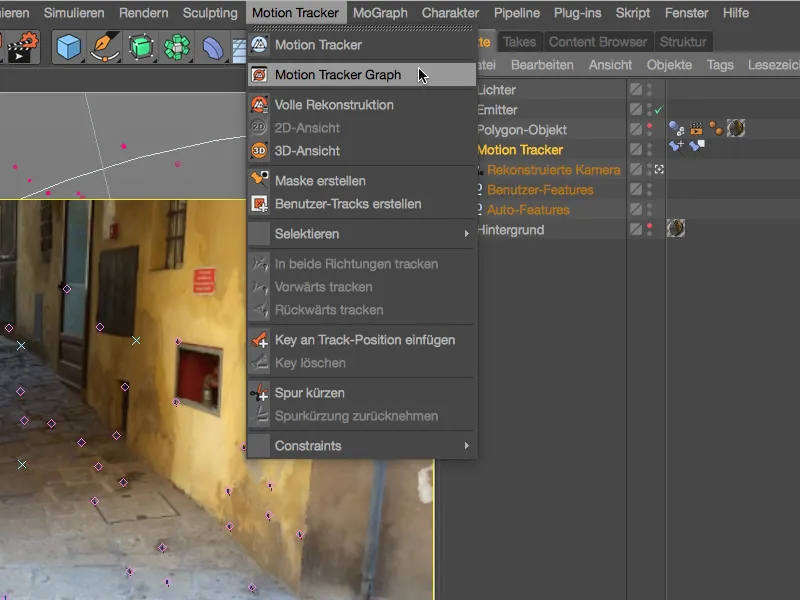
The column modeof the Motion Tracker Graph, which you can access via the symbol on the far left of the palette, provides a rough overview of the general quality of the existing tracks. The color gradient ranges from green (good tracks) to brown to red (bad tracks).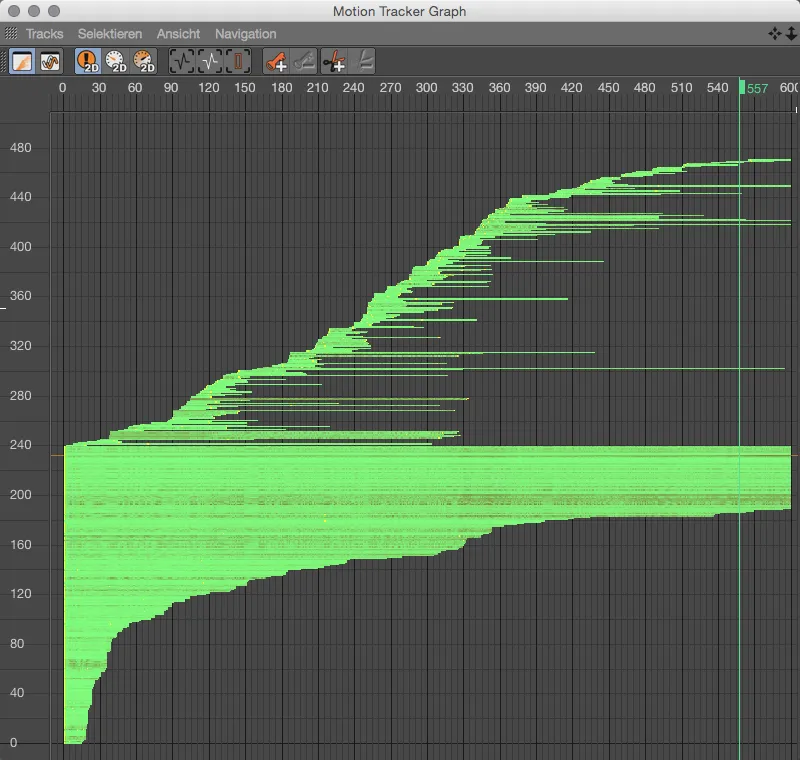
The curve mode, which we access via the curve symbolin the command palette, is more informative. Here we see each track individually plotted as a curve. In principle, it is desirable for the curve to be as even as possible, which is why we can quickly identify problematic peaks in the graph and react to them if necessary.
The image shows the 2D tracking errors, and we can also use the other buttons to display the 2D tracking speed...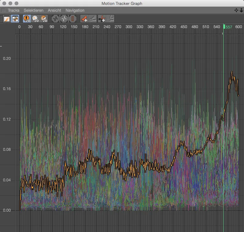
... and the 2D tracking acceleration. Acceleration peaks are often a very reliable indicator of problematic track jumps. If such a track belongs to the existing tracking points despite automatic filtering, a decision must be made as to whether the track really provides important information or can possibly be deleted. In the first case, the Motion Tracker Graph offers the option of inserting regulating keyframes or cutting off the problem area via its command palette.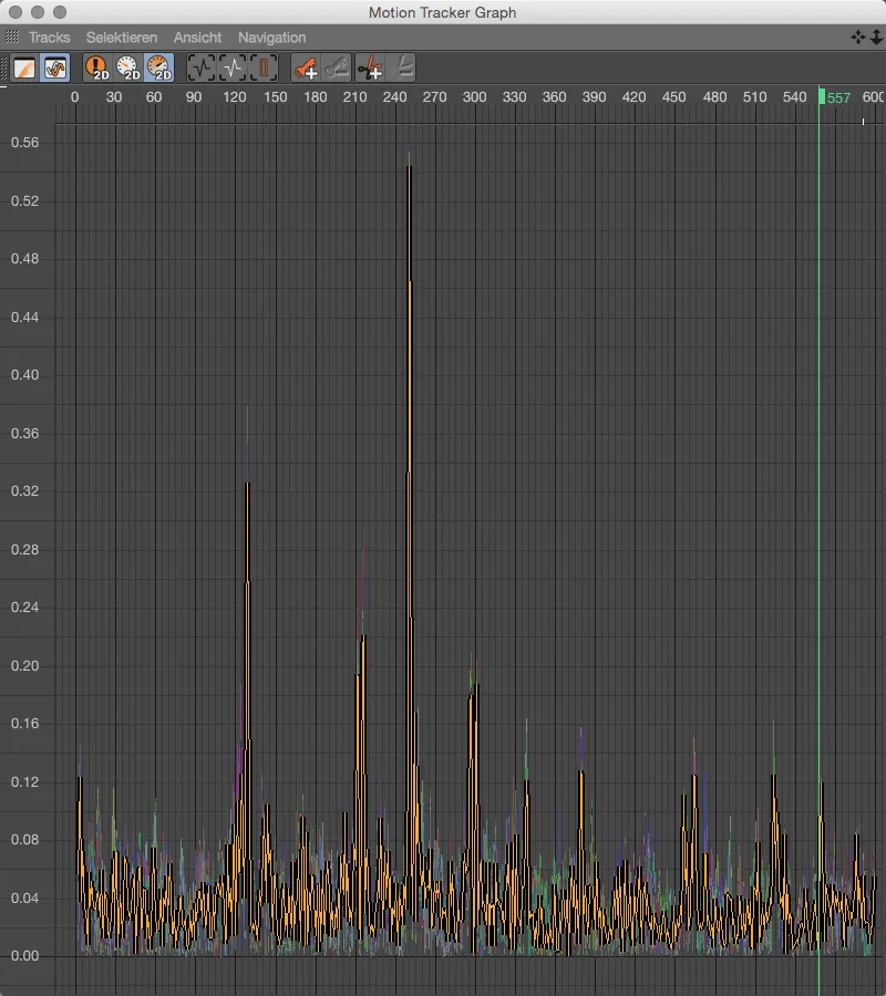
Rendering
When it comes to assessing the pure form of a model, colors or materials can be quite disturbing. It would be no problem to simply delete all texture tags in the Object Manager, create a new, light-colored material and assign it to all scene elements. The render setting Single material, which can be found in the render presets, is much more practical and less destructive.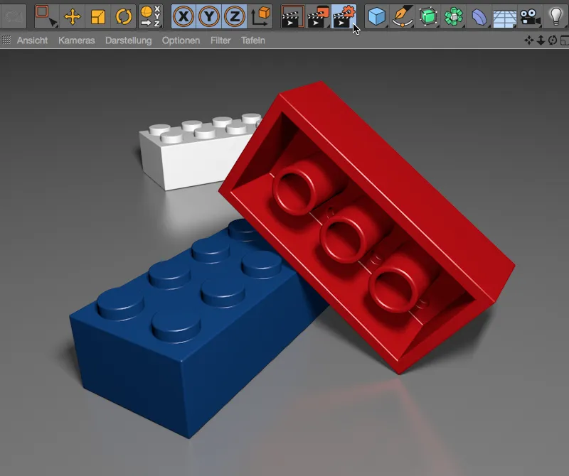
To activate this render option, we simply need to check the box in the left-hand column for Single material and make the desired render settings in the associated settings dialog. Let's first take a look at the result we get without any further action during rendering.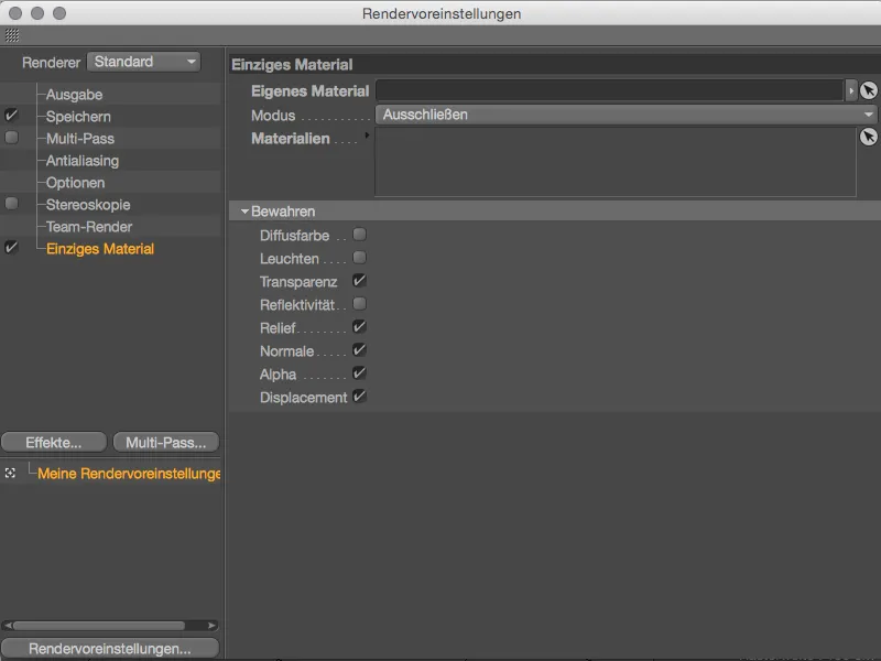
The colorful materials are no longer visible, both the Lego bricks and the floor are rendered in a simple, light gray. The term "clay rendering" used for this in technical jargon is easy to understand.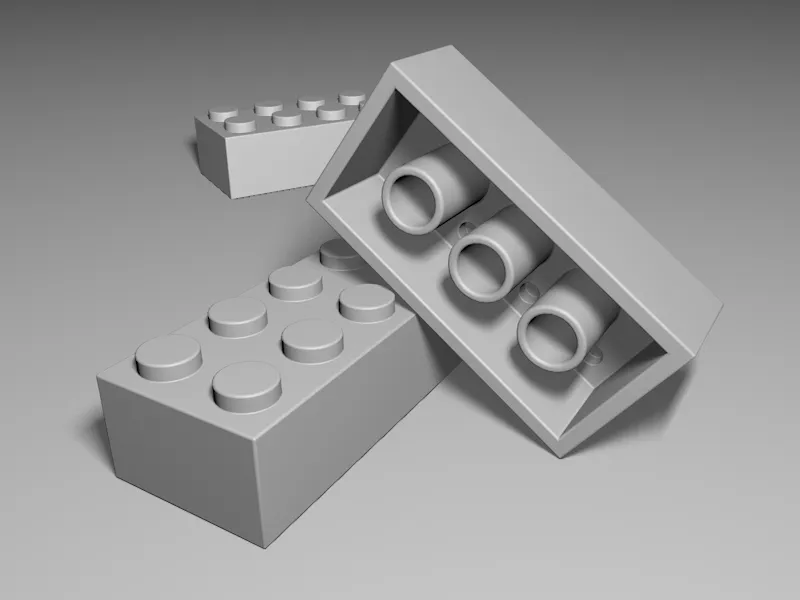
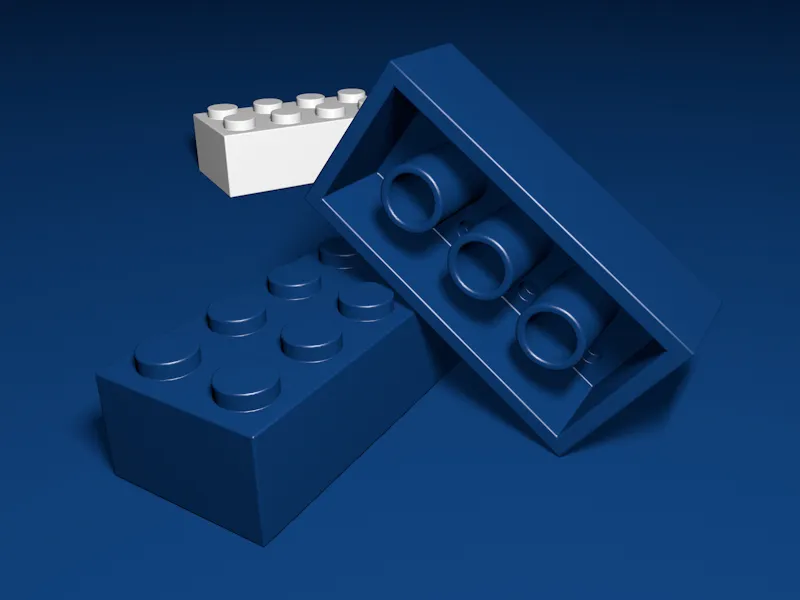
If, on the other hand, there is a base material that is to replace the other assigned materials during rendering, we drag it from the Material Managerinto the designated Custom material area of the render setting. In the example shown, all materials in the scene are to be replaced with the blue material; only objects with the white material remain unaffected.
In the Preserve section below, we can also specify which potentially important material properties should be retained when replacing. The Transparency, Relief, Normal, Alpha and Displacement channels, which are activated here by default, play a decisive role in the shape of a model.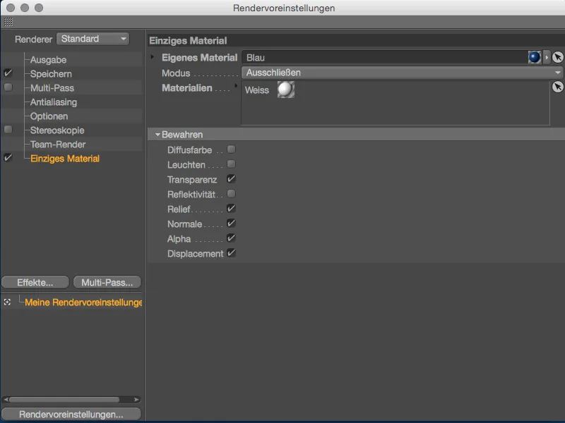
After clicking on the Render button, you can see that all elements of the scene have the blue material as desired - with the exception of the white Lego brick at the back, which we had excluded using the Exclude option.