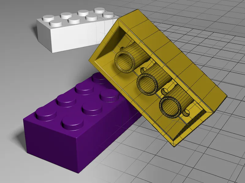
In the Lego brick tutorial on the bevel tool in Release 15, we have already modeled the Lego brick in detail, so in this tutorial we will focus on beveling the edges. Only the bevel deformer will be used for this.
The raw Lego brick model in the document "C4D_R16_Bevel-Deformer_start.c4d" is available as a starting point in the working files.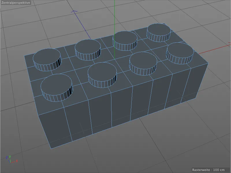
There are no chamfered or smoothed edges on the top or bottom of the Lego brick in our raw model. However, if the model is to look realistic, these sharp edges must be avoided or removed.

Applying a basic chamfer
In order to apply the bevels to our model as efficiently as possible, we combine all bevels of the same shape, radius and subdivision so that we can limit ourselves to just a few bevel deformers.
So let's attach the first bevel deformer to the model by selecting the Lego brick in the Object Manager and holding down the Shift key to get the bevel deformer from the deformation object palette.
Because we held down the Shift key, the bevel deformer we just created is automatically subordinated to the selected object, i.e. our Lego brick.
If you take a look at the corresponding settings dialog, you will quickly notice that the available parameters are almost identical to the bevel tool, with the exception of a few additional settings.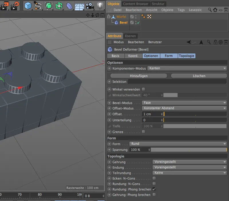
In the editor view, however, we see an immediate need for action. Although the bevel deformer did its job immediately and slightly chamfered all edges, it also caught the polygon edges on the flat sides of the model and the slightly angled edges along the nubs.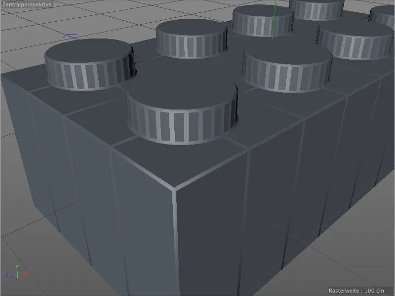
We can quickly eliminate this behavior of the bevel deformer by specifying an angle limit from which the beveling should take place. To do this, we activate the Use angle option in the settings dialog of the bevel deformer. The default angle threshold of 40° is a useful value for many cases, which is why we don't need to change anything here.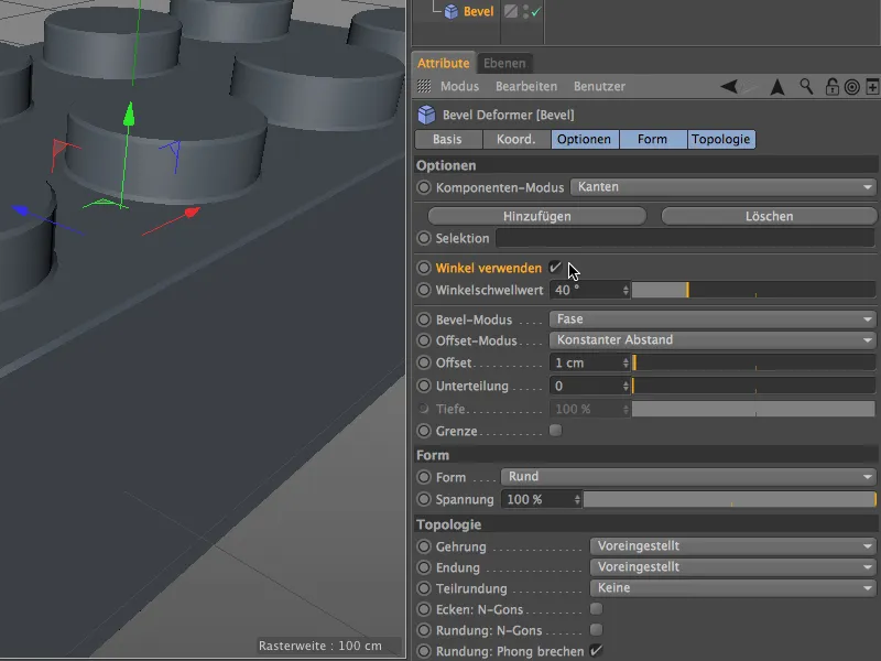
As we can see in the editor view, all unwanted bevels on the model surface have now disappeared; the bevel deformer is only still active on the edges to be smoothed. We now want to define this basic beveling exactly.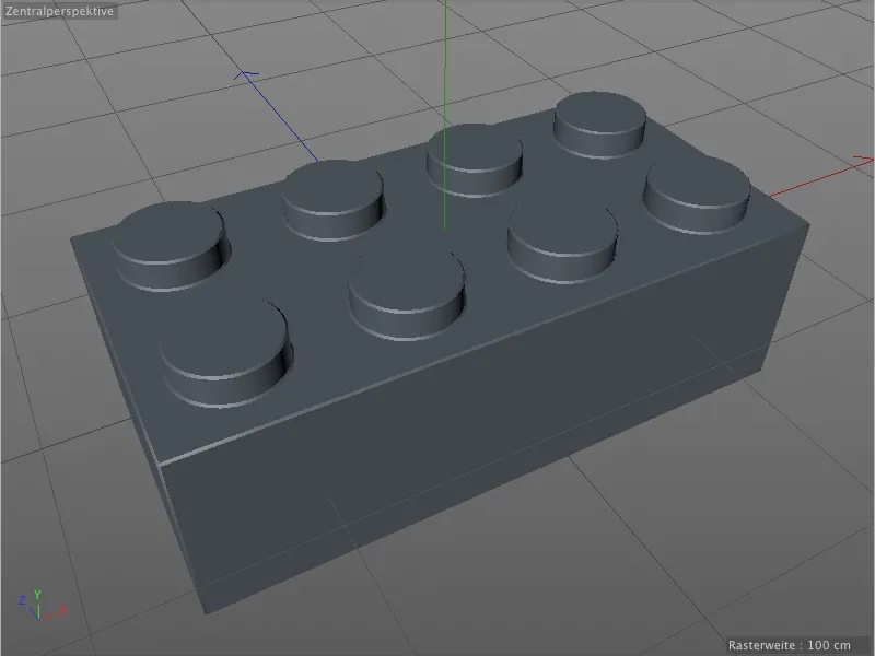
Bevel and offset mode with bevel and constant distance are perfect for our purpose, which is why we can concentrate on the offset and subdivision parameters. I have used an offset of 2 cm for the basic beveling, the subdivision is in the moderate range at 3. If you need extreme close-ups of the Lego brick, you may need to increase this value.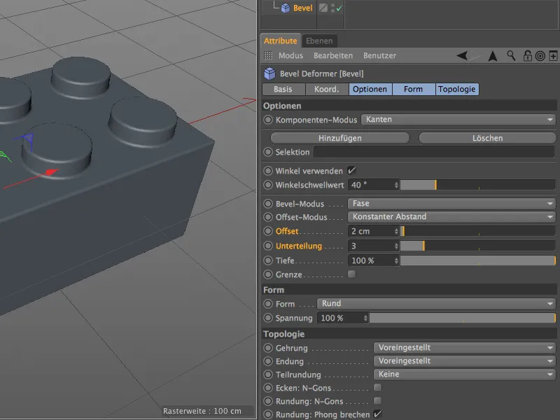
The basic beveling is now complete. As we have not defined any selections for this bevel deformer, it currently handles all edges that can be smoothed.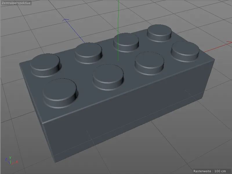
Of course, this does not only apply to the top side. The bevel deformer also does its job as expected on the somewhat more difficult underside with the fine holes.
Although all the edges are now chamfered, they all have the same radius. Although this looks acceptable, it is not suitable for a correct model of a Lego brick. We need additional bevels with different radii.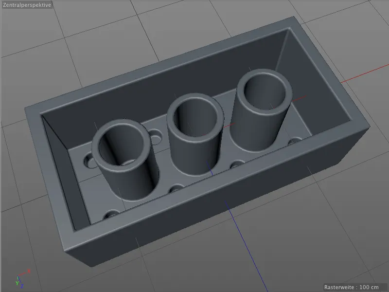
Finer edges with a second bevel deformer
We were able to proceed very generously with the basic beveling and did not have to consider any edges or make any selections. To make the following work with the edges easier, we activate the Quick shading (lines) display in the Display menu of the editor view.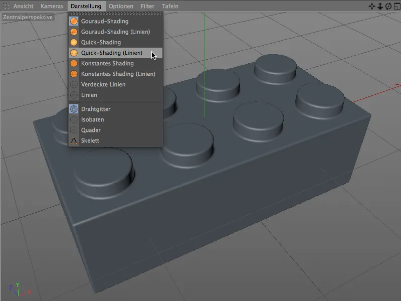
With this display mode, we can now also see how the bevel radius and the subdivision of the base bevel are reflected as a mesh on the model.
We now need the edges to be smoothed as a selection for beveling the bumps on the upper side. To create this selection, we activate the Edit edges mode from the tool mode palette and select the loop selection as a tool from the Select menu.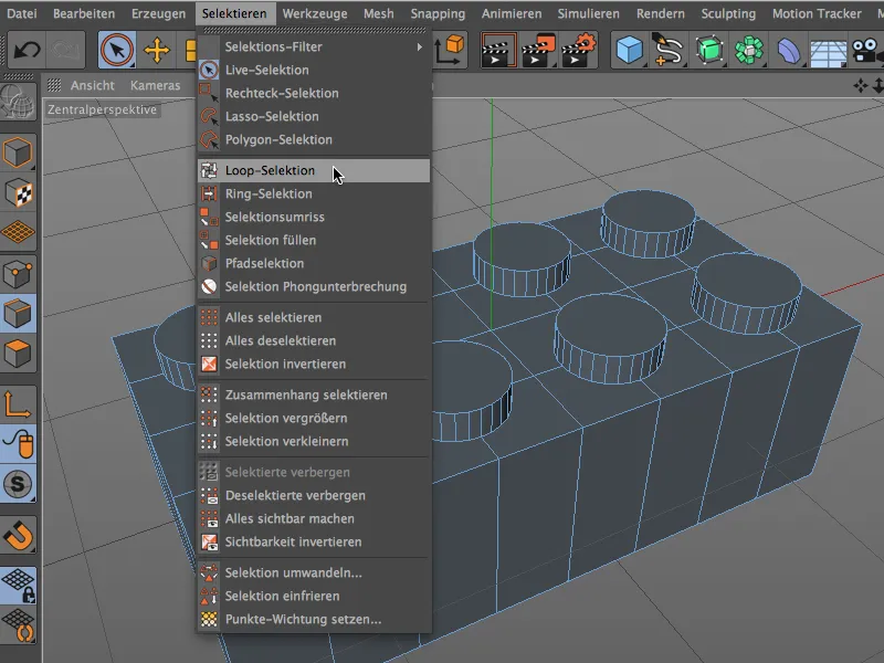
Holding down the Shift key, we now use the loop selection tool to create a selection of all eight edges on the top side of the Lego brick at the studs.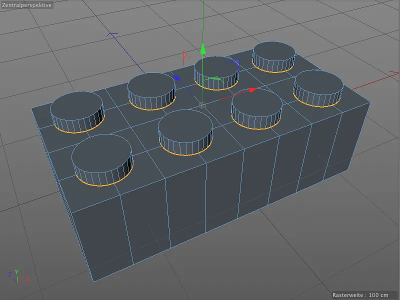
So that we can access this selection from the bevel deformer in the near future, we save it in a separate selection tag using the Freeze selection command from the Select menu for the model.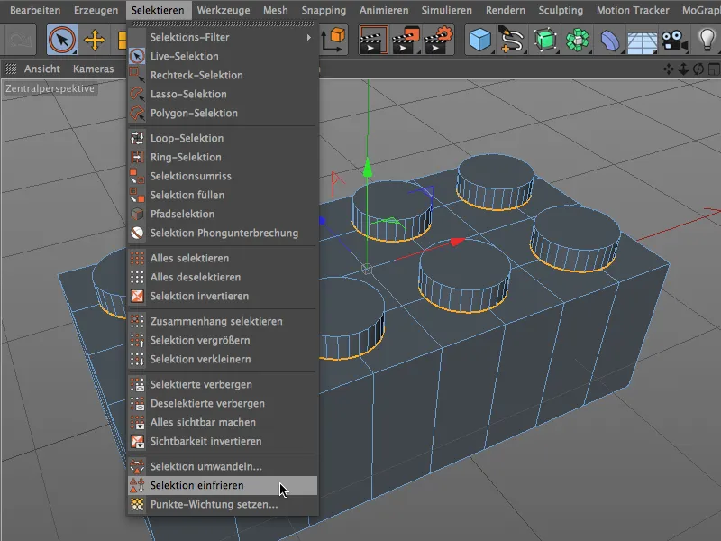
In order to give this newly created tag a unique name, we select it in the Object Manager and assign it a suitable name, for example "Bevel bumps top".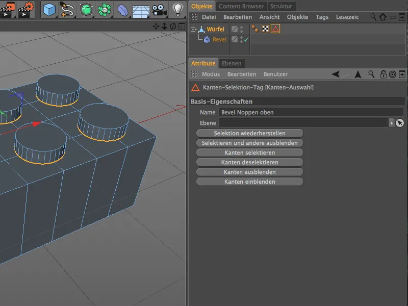
We need another bevel deformer so that we can now set different beveling specifications for the selected edges. We first select the polygon object of the Lego brick again via the Object Manager and hold down the Shift key to create the new bevel deformer as a sub-object of the Lego brick.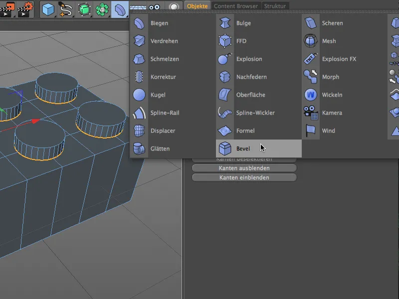
First, we give the second bevel deformer a unique addition after double-clicking on its name so that we can distinguish between the different bevels in the Object Manager. I decided to add the word "fine" because the transitions to the bumps should be more delicate than the base.
We then drag the edge selection we created for the studs on the Lego brick in the Object Manager from the polygon object into the Selection field in the "Fine" bevel deformer settings dialog. We can also apply the angle threshold known from the base bevel to this second bevel deformer and activate the use of the angle.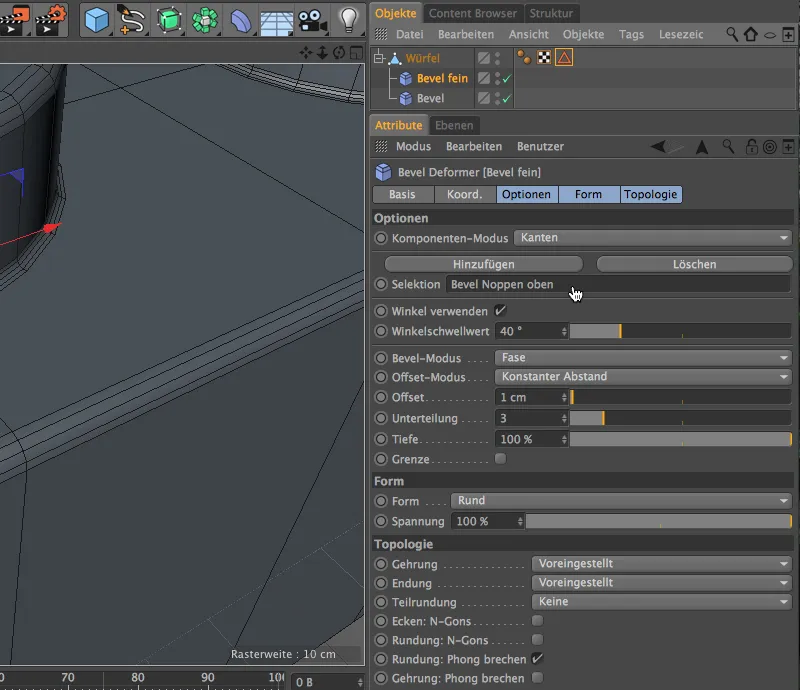
Using the offset and subdivision parameters of the bevel deformer, we can now carry out the beveling via its settings dialog. Zoom in a little closer to the bump transitions to better assess the effect of the parameters. As we are working with a bevel deformer and therefore non-destructively, we could easily change the parameters afterwards or simply delete the beveling together with the deformer.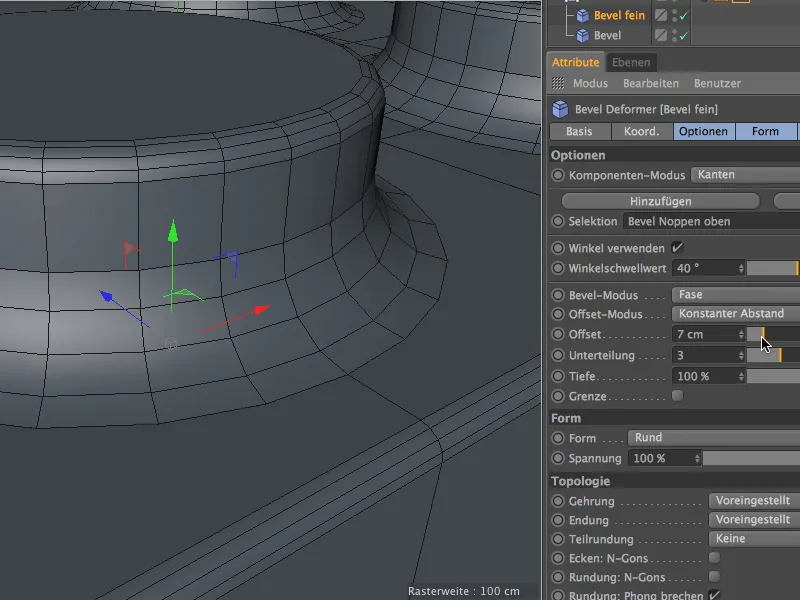
In the end, I decided on an offset value of 1 cm for this fine beveling. In the editor view, this can be assessed very well due to the shading mode with the lines.
Now let's take a look at where we can still use this fine beveling on the Lego brick. On the top side, all edges are chamfered correctly so far, ...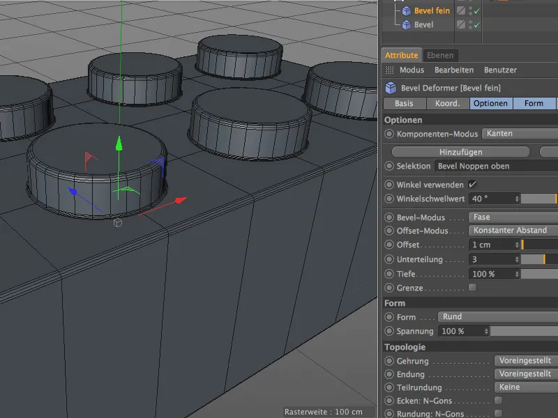
... but on the underside or inside of the Lego brick we find further edges for the fine beveling in the small holes below the studs. We activate the edge-editing mode and the loop selection tool and select the circular edges at the top and bottom of the holes by holding down the Shift key, as shown in the following illustration.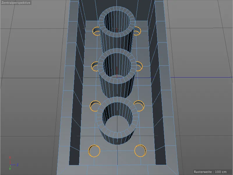
We save the selection we have just created in a new selection tag. Before calling the Freeze selection command from the Select menu, make sure that the existing selection tag is not selected, otherwise it will be overwritten.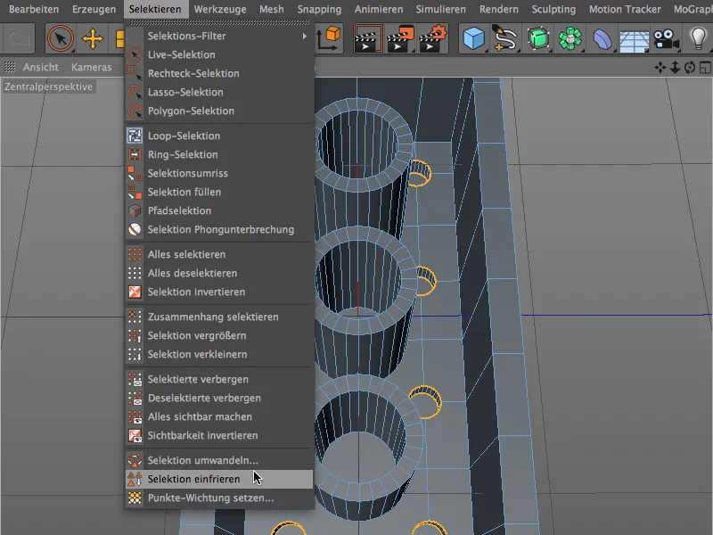
You should now see a second selection tag on the polygon object of the Lego brick in the Object Manager. In the settings dialog of the tag, we again assign a meaningful name for this edge selection.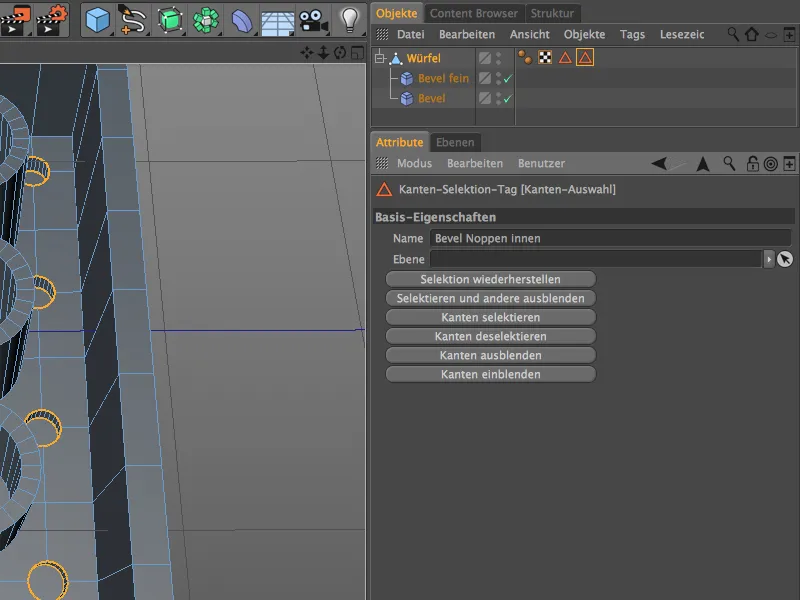
The edge selection just created should also be given the fine beveling. We already have a bevel deformer with the correct parameters, we just need to assign the new selection to it. To do this, we click on the Add buttonabove the existing selection in the Options area of the Bevel Deformer settings dialog.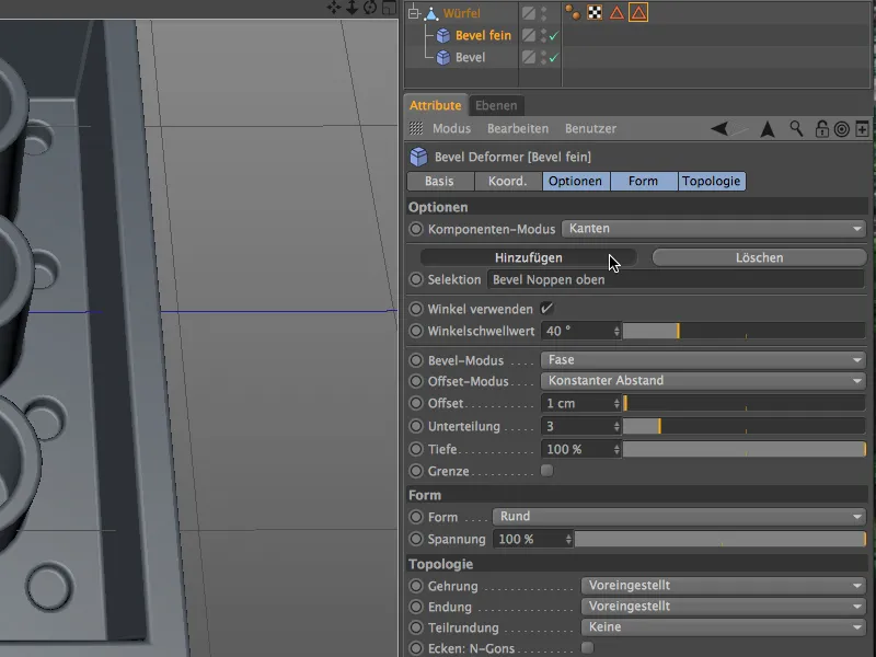
A new field for defining a further selection has been added. We can now drag the second edge selection from the polygon object of the Lego brick into the settings dialog of the bevel deformer.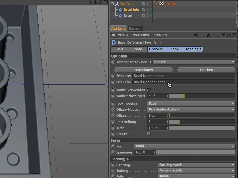
A closer look at the underside or inside of the Lego brick in the editor view shows that the fine bevels work correctly and do not cause any problems in the mesh.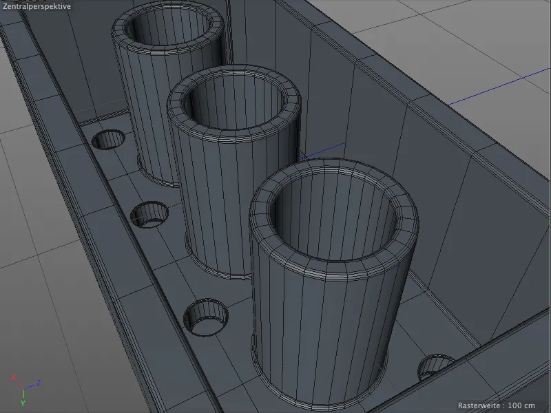
Large bevels for the tubes of the Lego brick
The bevels on the upper edges of the tubes don't look bad, but they don't correspond to reality. They are actually more rounded to make it easier to fit the Lego bricks together.
We will need another bevel deformer for these new bevels. First, however, we create a new edge selection for the top edges of the tubes for targeted beveling. We hold down the Shift key, activate the edge selection mode and use the Loop selection tool to select the outer edges of the top of the tube.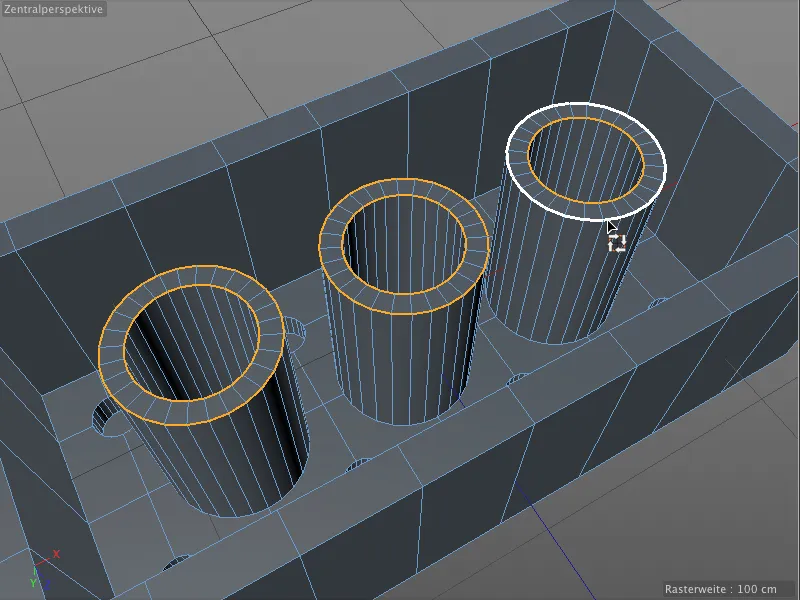
We then save this edge selection in a new selection tag using the Freeze selection command from the Select menu. Again, make sure that no other selection tag is selected.
In the settings dialog of the edge selection tag, we assign a unique name to keep track of the various selections.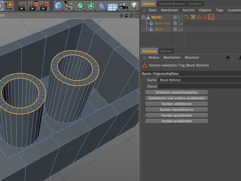
As already mentioned, we need an additional bevel deformer for this larger beveling. We get it from the deformation object palette by holding down the Shift key in order to subordinate it to the polygon object of the Lego brick.
This deformer is also assigned a unique name. In its settings dialog, we drag the edge selection tag for the top of the tube into the Selection field so that the deformer only affects these areas.
With an offset valueof 3 cm and a subdivision of 5, we get significantly rounder edges on the top of the tube.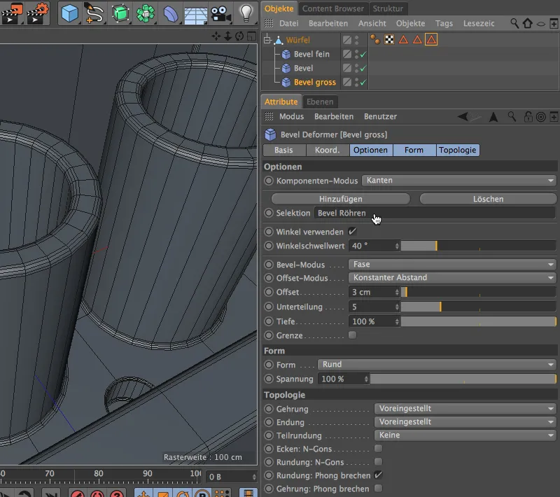
At least in theory. However, if we take a closer look at the bevels in the editor view, we cannot recognize any changed rounding.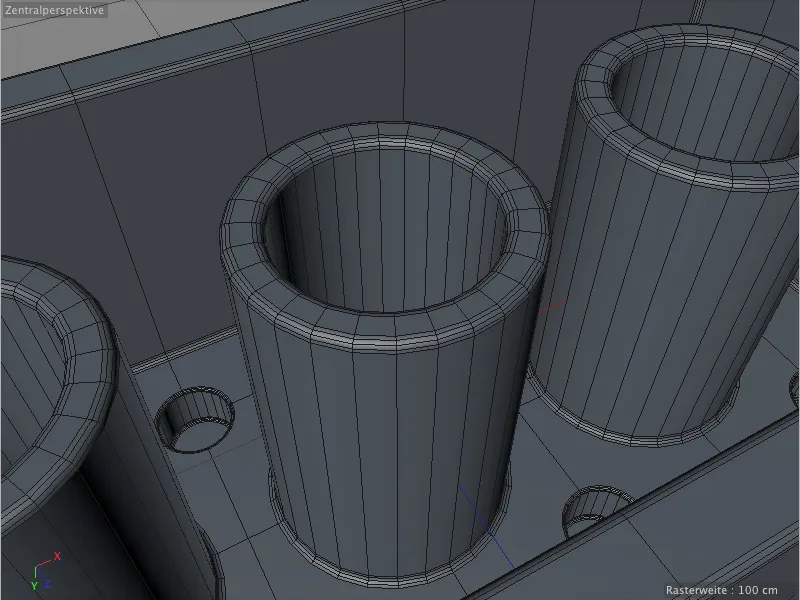
Do you also have this error? I admit that I created this situation by deliberately placing the last bevel deformer at the bottom of the object hierarchy. If we put the deformer with the large bevel at the top of the Object Manager, the beveling on the top edges of the tubes looks much better.
The order in which the bevel deformers are executed makes a big difference. In our case, the base de former does not affect a defined selection, but all edges that have not yet been beveled. Therefore, if we want to save a separate selection for this deformer, it must be placed last in the deformer sequence in the Object Manager.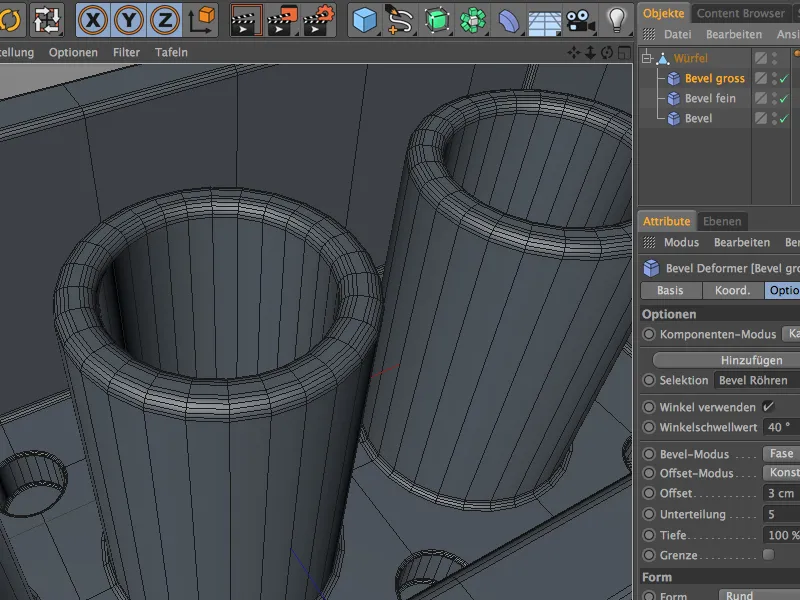
This means that these bevels now also work correctly and our Lego brick is fully modeled.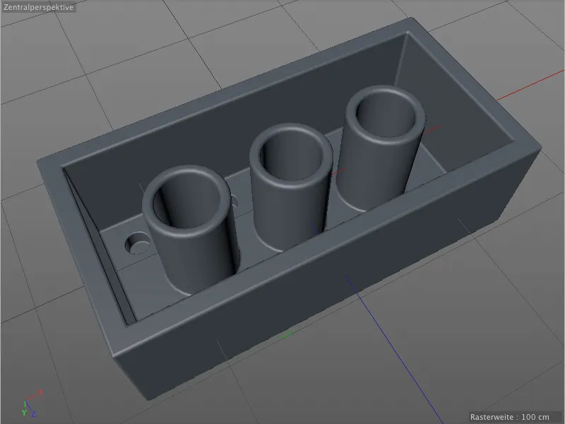
The big advantage we now have compared to the bevel tool: Thanks to the deformers, we can also change, replace or completely delete the edge bevels at any time afterwards.