What is particularly pleasing about the new reflectivity channel is that it is available to every Cinema 4D user, regardless of the program version. However, anyone opening the associated settings dialog for the first time will get lost in the multitude of parameters.
In this tutorial, I would like to give you an introduction to this great new R16 feature to make your first steps easier. We'll take a look at how painted surfaces, metals and textiles can be realized with the new reflectivity channel with relatively little effort. In the working materials package you will find all the materials shown in this tutorial in three different Cinema 4D scenes.
Painted surfaces
The new reflectivity channel is a blessing for the realistic creation of materials for painted surfaces, as it allows us to recreate the structure of such a surface using layers.
Let's start by double-clicking on a free space in the Material Manager to create a new material. For my blue paint surface, I have renamed the material accordingly.
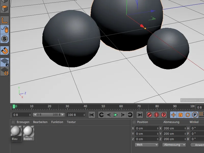
To create this first material, we only need two material channels, the color channel and the reflectivity channel. If you haven't already done so, activate these two channels via the base page of the material in the Attribute Manager.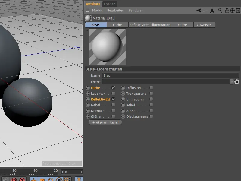
I have selected a rich blue as the basic color of the material in the color channel. Incidentally, another small change from Release 16 can also be seen in this channel: The illumination model is now stored here and no longer in the Illumination channel.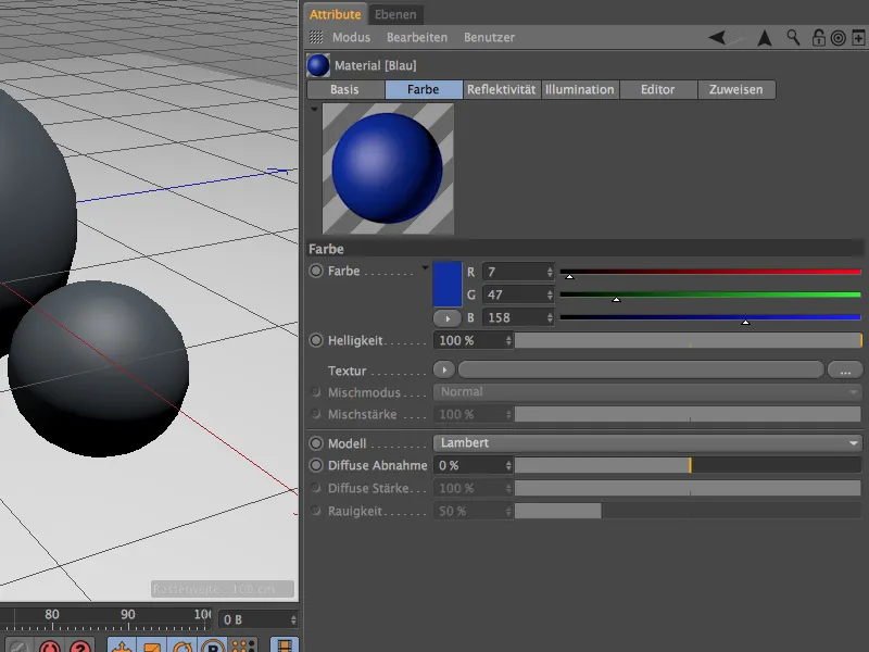
If we now select the reflectivity channel in the attribute manager, we will find the previous highlight as a standard within a structure organized via layers. The previous highlights and reflections therefore still work in version 16, but they are marked with the addition "(old)".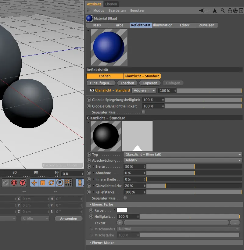
However, as we want to use the new functionality of the reflectivity channel, we simply delete this unneeded highlight layer by selecting it and clicking on the Delete button.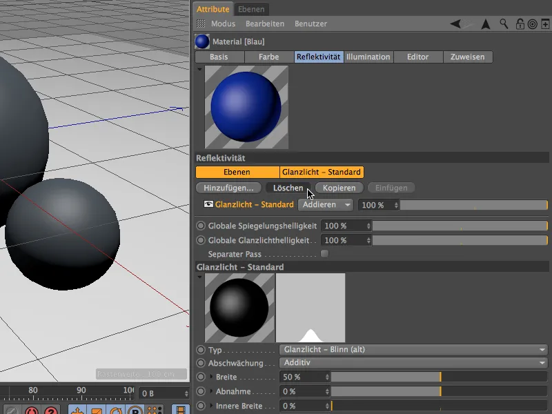
All the layers required or possible for the reflectivity are displayed in the menu after clicking on the Add... button. At the bottom we see the old reflections and highlights, in the middle some diffuse models, which in principle correspond to the color channel and are therefore hardly needed.
Things get more interesting with the Beckmann, GGX and Ward types. These models differ in the way the reflection is attenuated by the angle of reflection. Beckmann works physically correct and fast, while GGX is slightly better suited for metals. Ward is recommended for soft surfaces such as rubber.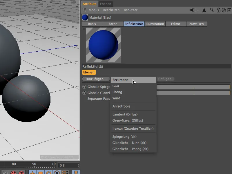
We decide on a Beckmann type layer and, for the sake of clarity, rename it "Base" in the Layers area after double-clicking on the layer name. In this example, this "base" layer is to be given the color and surface properties, after which we apply a "clear coat" using a second layer. Based on a glossy paint, I have opted for a low roughness, a medium reflection strength, a clear highlight and a medium relief strength.
With the latter parameter, we can test how the reflectivity channel deals with bump maps at this point. To do this, we fold down the small triangle next to the relief strength and find the Mode menu, in which we can specify our own relief map.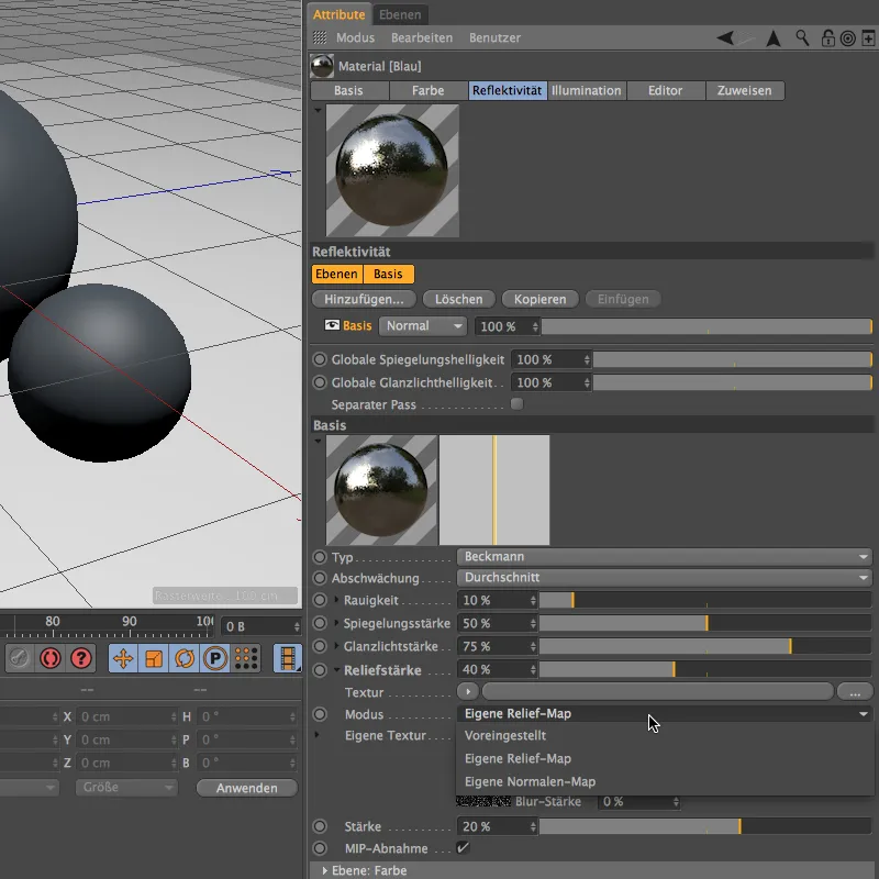
Now we have a separate entry for our own texture. Click on the arrow button to open the Shader menu and select the noise shader for the relief map.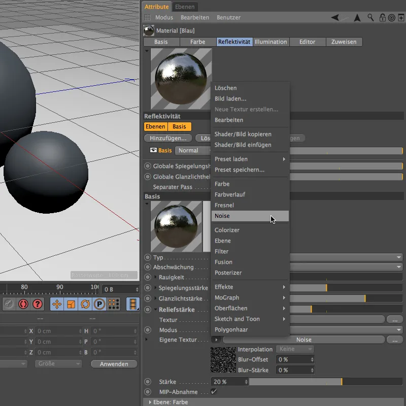
After clicking on the noise shader button, we find ourselves in its settings dialog. The Nutous shader has a nice grain, and we reduce the global size of the shader to 20% in order to obtain small but still noticeably visible bumps.
To emphasize the grain a little more, we also want to color it. In order to be able to continue working with the same shader settings, we save the parameters to the clipboard using the Shader>Copy Image command in the Shader menu of the arrow button.
A little further down in the settings dialog for the reflectivity layer is the Layer: Color section. In the Color entry there, a shader menu is again available via the arrow button, which we use to insert the saved noise shader.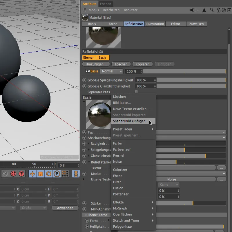
By clicking on the Noise button of the inserted shader, we have access to its parameters. In contrast to the relief map, we specify two suitable colors for the coloring of the bumps. The remaining shader settingsremain unchanged so that they match the relief map.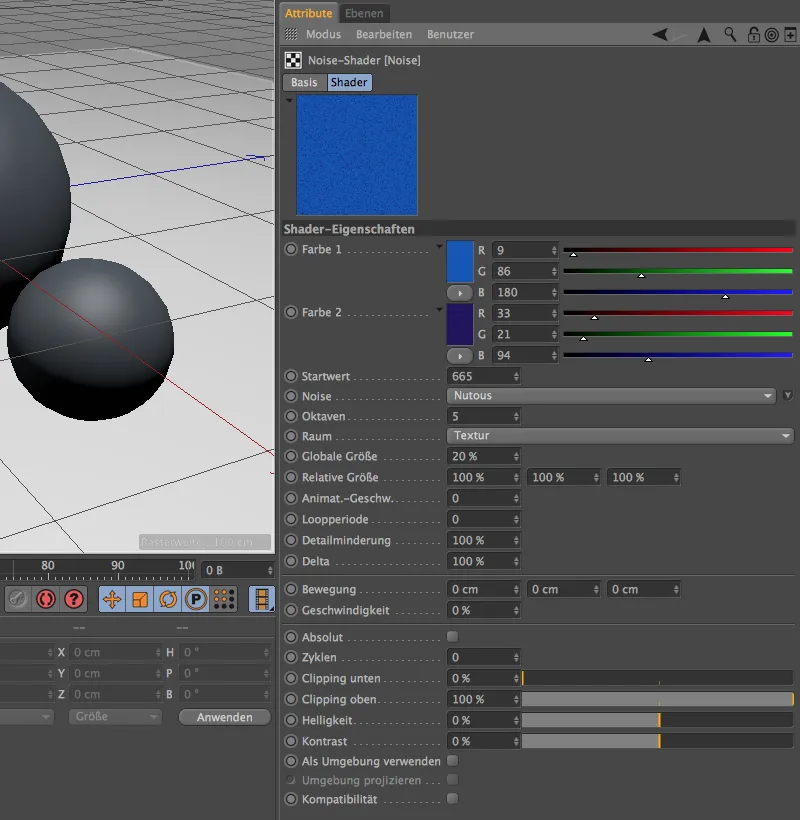
We have already defined our base layer and will now apply a virtual "clear coat" using another layer. To do this, we click on the Add... button at the top of the settings dialog of the reflectivity channel and select another layer of the Beckmann type.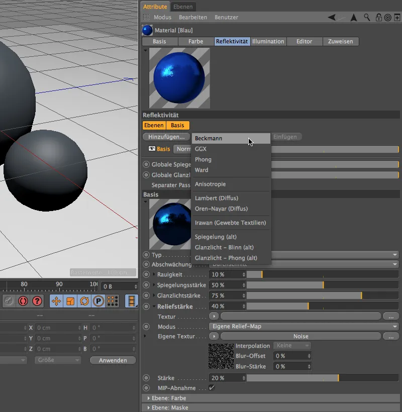
Because clarity is a precious commodity in the reflectivity channel, we rename the new layer to "Clear varnish". In the adjacent menu of the calculation mode, we select the Add mode to add the properties of the clear coat layer above to the base layer.
For the clearcoat itself, we assign a roughness of 0%, a very high specularity and a specularity of around 30%. Feel free to experiment a little with the values to get a feel for the effect of the settings.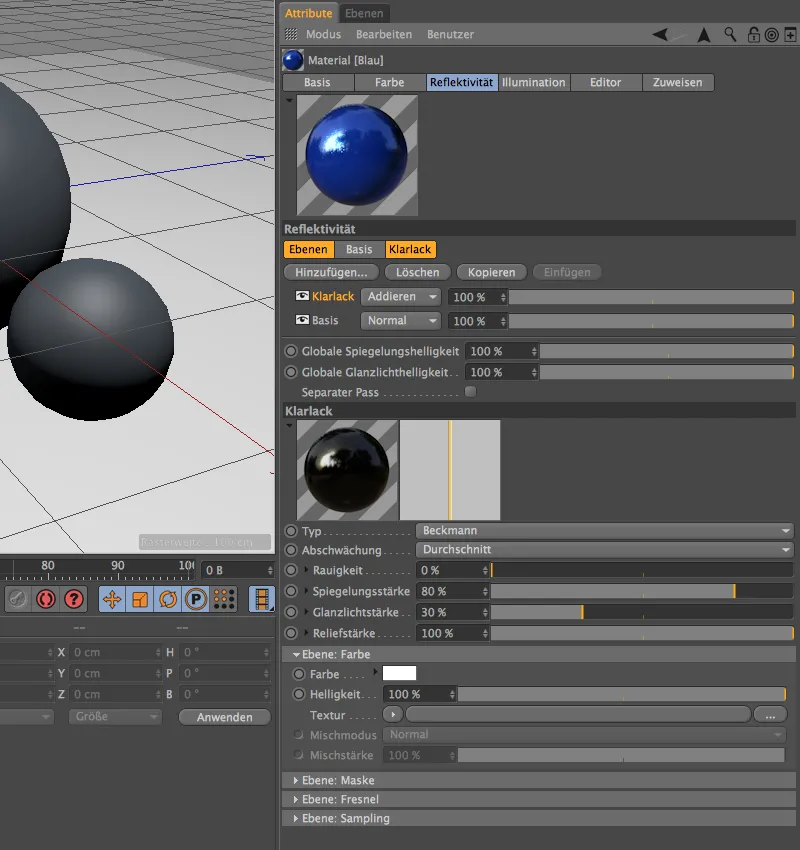
Further down in the reflectivity channel we find one of the most important sections: Levels: Fresnel. Here you will find a number of presets that reproduce the behavior of materials and surfaces as realistically as possible.
Our "clear coat" is naturally close to glass in terms of its properties. We therefore select the Fresnel type Dielectric to obtain presets for this type of material.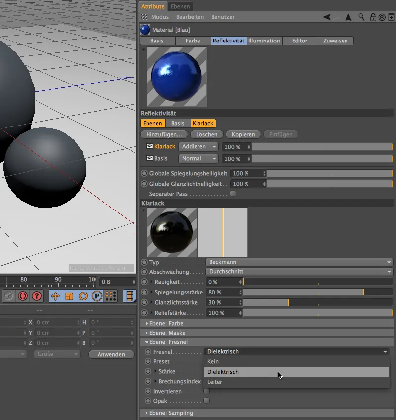
We open the Presets menu and have a good range of transparent materials and liquids in front of us. The Glass preset comes closest to our clear lacquer.
After this last setting, our first material with the reflectivity channel is ready. It should be noted that we have only just touched on the possibilities of the new channel, as we have only used two layers. The result is nevertheless impressive.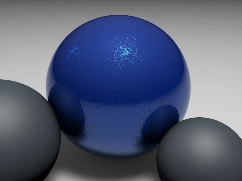
Let's move on to another example to see how we can generate matt-looking surfaces with the reflectivity channel. In a new material, I opted for a dark red with a slight blue component in the color channel.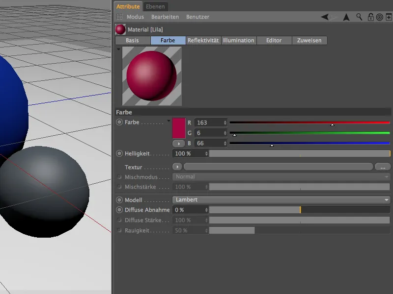
In the reflectivity channel, we delete the unneeded standard glossy light and replace it with a Beckmann type layer. The decisive factor for the matt appearance is of course the roughness parameter, where we use a relatively high value of 50%. Nevertheless, the material should be highly reflective and show a clear highlight - if you look at the material preview, you will know that I am aiming for a Christmas tree ball.
The bauble should therefore be flawless, which is why we leave the Relief field empty. Instead, we specify a color for the reflection and highlight under Layer: Color; in this case, pink fits quite well.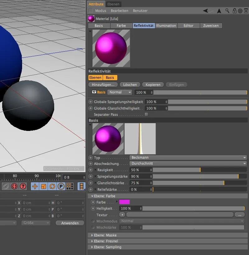
Finally, we give the sphere a special look by adding an additional layer with clear varnish. As you can see from the buttons above the layers, you can easily copy layers and paste them elsewhere. We can continue to use the clear varnish layer from the first example here. In contrast to this, however, we select the Diamond preset with an even stronger refractive index under Layer: Fresnel.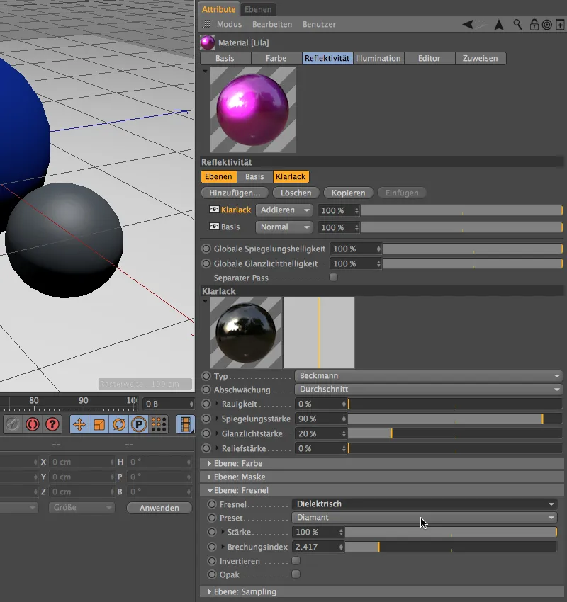
In the rendering, the sphere looks quite attractive, but there are unsightly distortions, especially in the darker areas.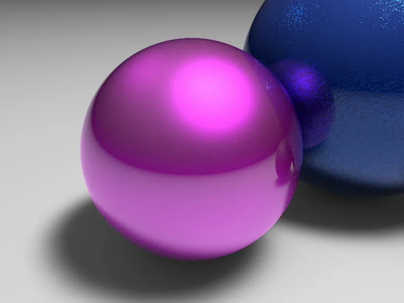
As is so often the case with such disturbing effects, the reason for this is insufficient sampling. The reflectivity channel has a sampling area for each layer. In our case, the base layer is affected, so we increase the sample subdivision from the default 4 to 6.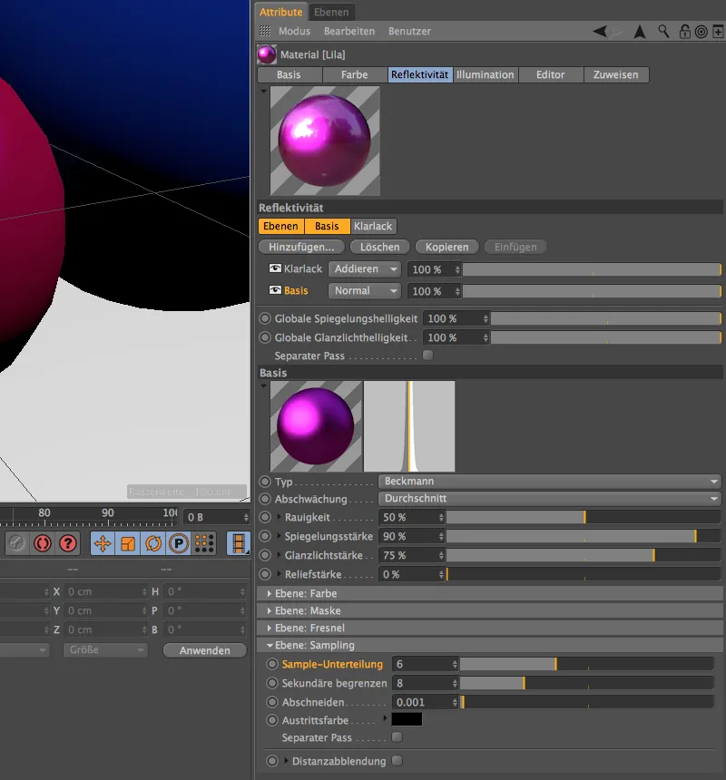
The disturbing points are now barely visible in the new rendering. We can set the sample subdivision even higher, but then we will have to live with even longer render times.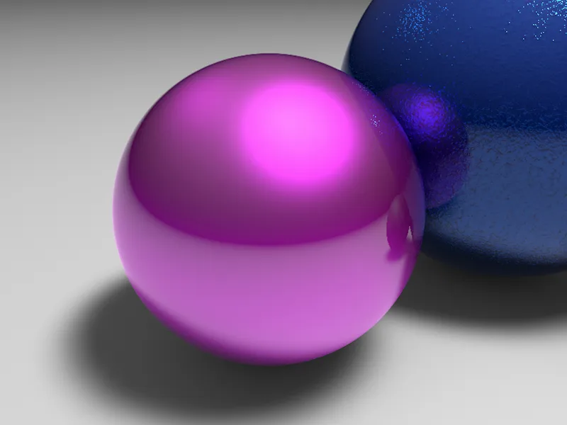
In a final example, let's take a quick look at how quickly we can create a car paint job with the new reflectivity channel. This time we can use a strong red in a new material in the color channel.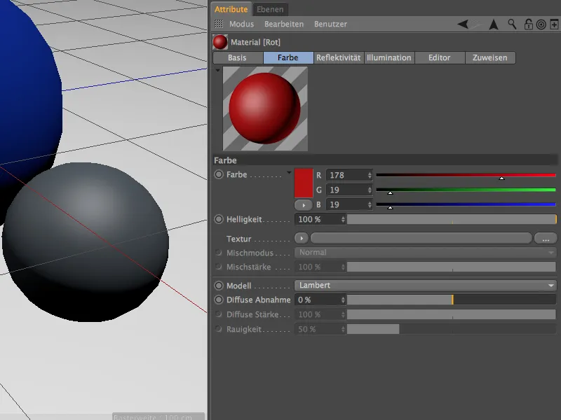
In the base layer, there is a lower reflectivity layer of type GGX with a slight roughness with a medium specularity and a high specularity.
To simulate small metallic particles, there is a noise shader as a relief map and under Layer: Color.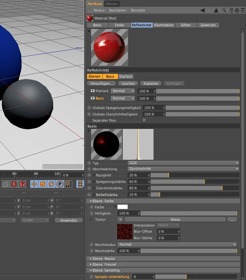
A look at the settings dialog of the noise shader shows the small global size of 1%. The noise for the particles has also been slightly sharpened by clipping.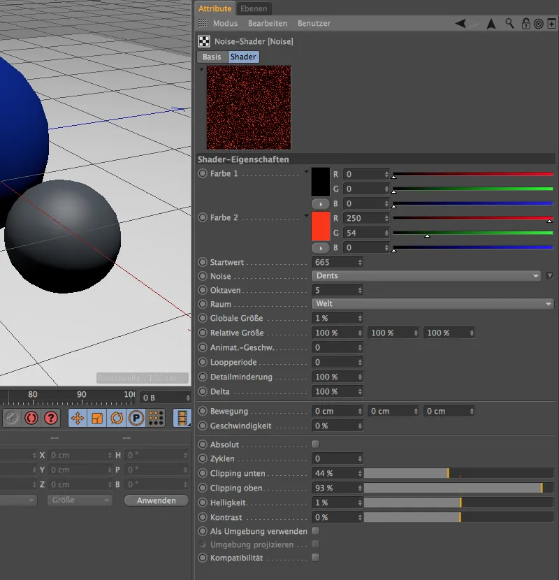
We are already familiar with the clear coat layer above it, but this time I opted for the emerald preset for Layer: Fresnel.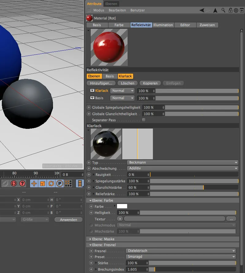
Finally, the final rendering, in which we can see our three variants of the different paint surfaces in comparison. For our introduction to this topic, I only used two layers in the reflectivity channel for each material. However, there is nothing to stop you from working with even more layers and defining the paint surfaces in even greater detail.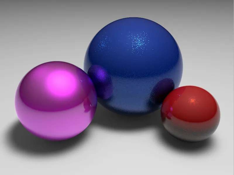
Metal surfaces
We have already become familiar with the extensive settings dialog, but so far we have concentrated on the paint surfaces. However, the reflectivity channel is also ideal for creating metal surfaces. The materials created in this section can be found in a separate Cinema 4D document in the working files.
We will create a new material with a color and reflectivity channel. The standard color can remain as it is for the time being; we will now focus primarily on the reflectivity. As usual, we first have to get rid of the layer with the standard glow using the Delete button.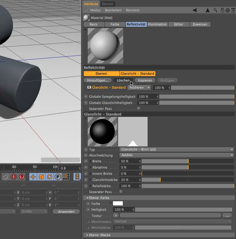
Instead, we create a layer for anisotropy as the first layer for the reflectivity using the Add... button. This layer can be used to generate the traces of finished or processed metal very nicely.
We then select the Metal setting to attenuate the reflectivity. We can now define its properties using the already known parameters for roughness, specularity, specular light and relief strength.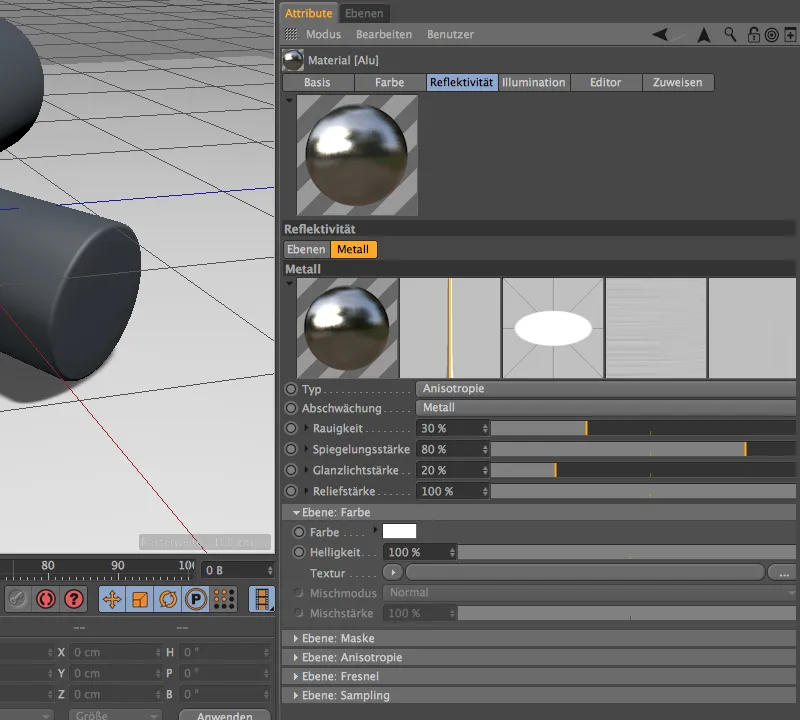
If we open the Layer: Anisotropy section a little further down, we see a large number of parameters for creating processing and ageing marks on the metal in front of us. This also includes the three additional previews next to the material preview of the reflectivity layer.
Here we first select the type of reprojection for the anisotropy. The Planar option means that the grooves are projected lengthwise onto the piece of metal.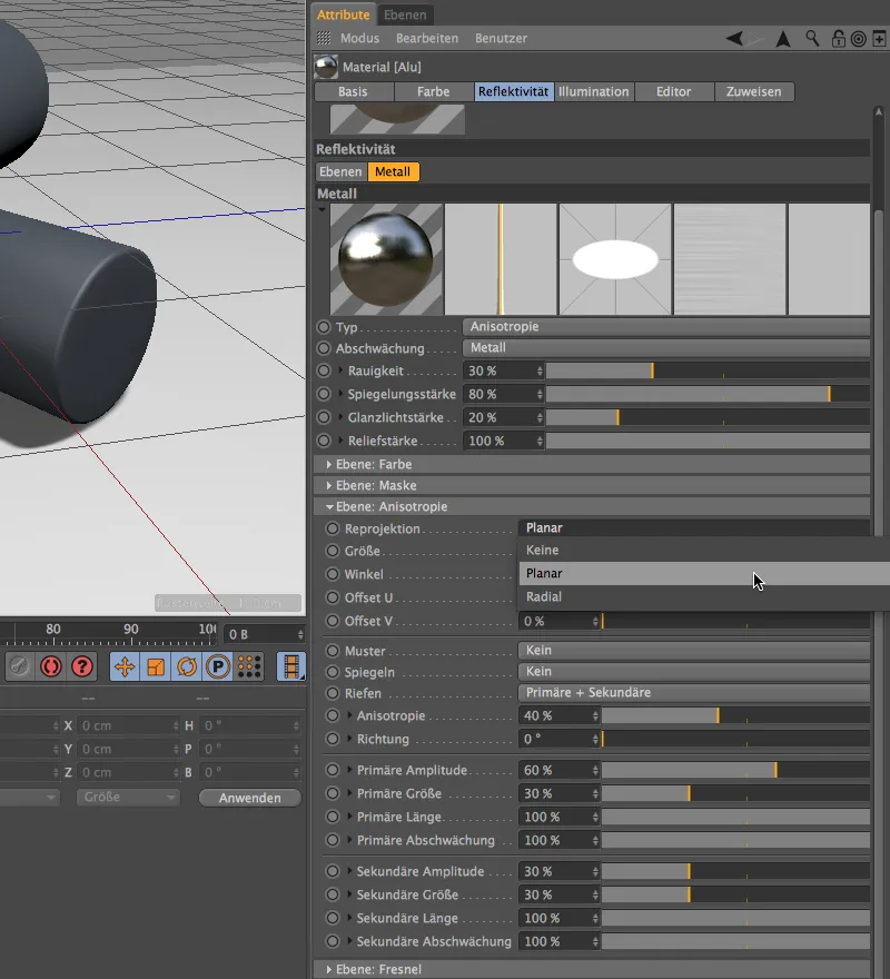
Like most other settings, the correct size of the anisotropy can only be determined by test renderings. You can therefore either accept the parameters directly or experiment with the settings yourself. The Primary + Secondary selection for the grooves allows us to apply additional grooves parallel (primary) and perpendicular (secondary ) to the finest tracks specified by reprojection. I would like to dispense with a pattern for this example.
Further down in the settings dialog we find the familiar section Layer: Fresnel. There are also suitable presets for metals here. To do this, however, we must first set the conductor type for a metal in Fresnel.
In the Preset menu, we now find a whole list of common metals; for this example, I have chosen aluminum.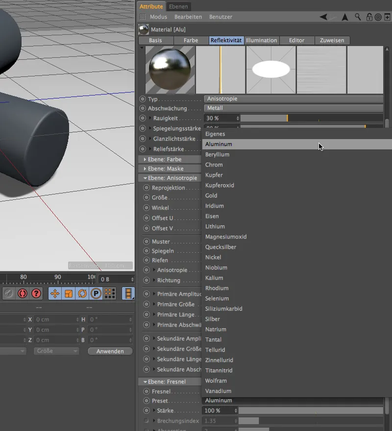
The base layer for the first metal is now complete. However, as metals usually also have a thin, additional coating, our aluminum is also assigned an overlying clear coat layer. You can copy it directly here or copy it from the blue paint material and paste it here.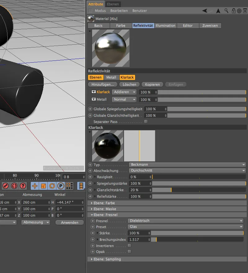
High time for a rendering of our aluminum material. Applied to a cylinder, the directions of the reprojection and the primary and secondary grooves can be seen very clearly.
To get to know the difference between the anisotropies and presets better, we create a copy of the aluminum material using the Material Manager and try our hand at the precious metal gold.
In the settings dialog of the reflectivity channel, we jump directly to the metal layer and take care of the anisotropy. To make the processing traces more visible, we increase the size to 100% and set an angle of 300°. Again, primary and secondary grooves should be visible, but this time in a grid pattern. As you can see in the Pattern menu, in addition to the Grid, Circle, Diamond and Diagonal options, you are also free to create your own patterns.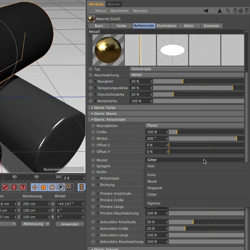
At the bottom under Layer: Fresnel, we now switch to the appropriate preset. Gold also belongs to the ladder group.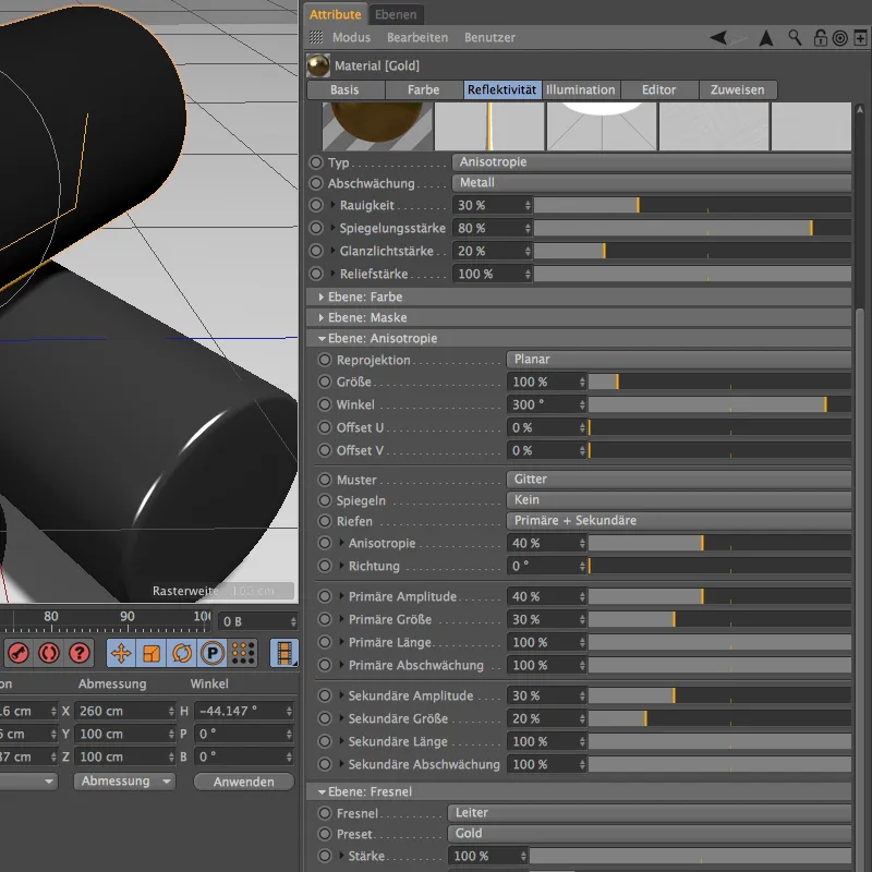
As you have already seen in the preview image of the reflectivity channel, the preset alone has given the metal a gold color. We can enhance this coloring a little more by also setting a light orange as the reflectivity color under Layer: Color.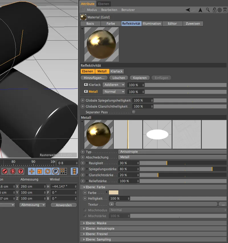
The finished gold materialcan now be assigned to an object. As the rendering shows, the golden cylinder has the desired angulation and the grid pattern for the primary and secondary grooves.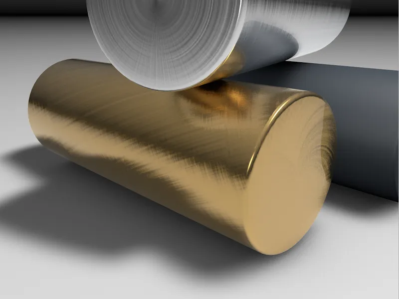
For the last of the three cylinders, I would like to show in comparison how a metal behaves without the clear coat we created. To do this, I copied the aluminum material once again and removed the clear coat layer.
The roughness was further increased, while the reflection and gloss were greatly reduced. Only primary grooves should simulate "raw", largely unprocessed iron.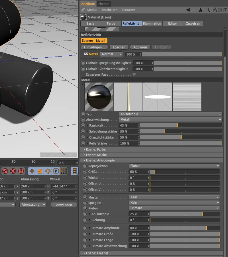
Of course, there is also a preset for iron in the presets menu under Layer: Fresnel. Due to the rather rough surface and the lack of a coating layer, it is advisable to keep an eye on the sample subdivision. With a value of 6, the result should not be too grainy.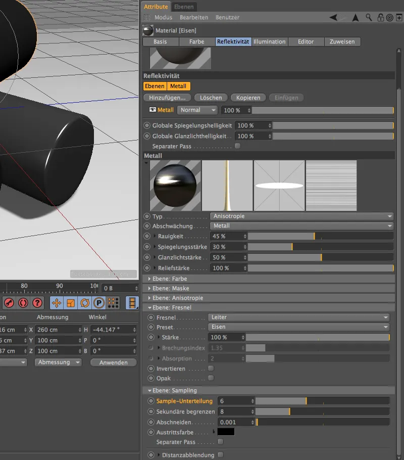
In the last rendering of our metal surfaces, the iron cylinder shows only primary grooves without patterns, as intended. Compared to the other cylinders, the lack of coating is clearly visible.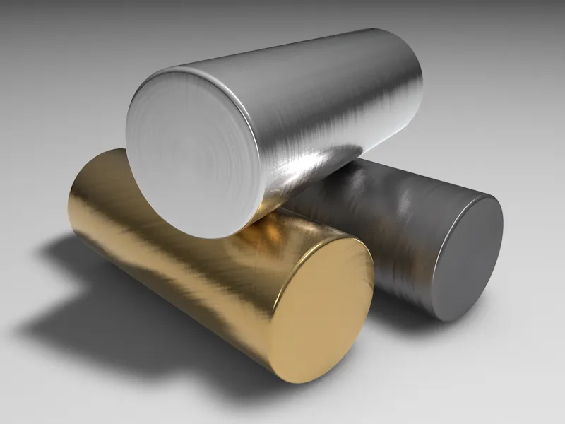
Fabric and textiles
Based on the paint and metal surfaces treated so far, fabrics and textiles are somewhat out of line. However, the reflectivity channel is also ideal for creating realistic fabrics.
You can also find the finished textured scene for this example in a separate document in the work files.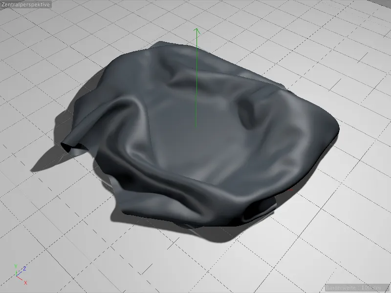
We will create a new material for texturing the fabric polygon object. We will make all the settings in the reflectivity channel, so we can safely deactivate the color channel.
In the reflectivity channel, the first thing we will do is to remove the default highlight layer using the Delete button.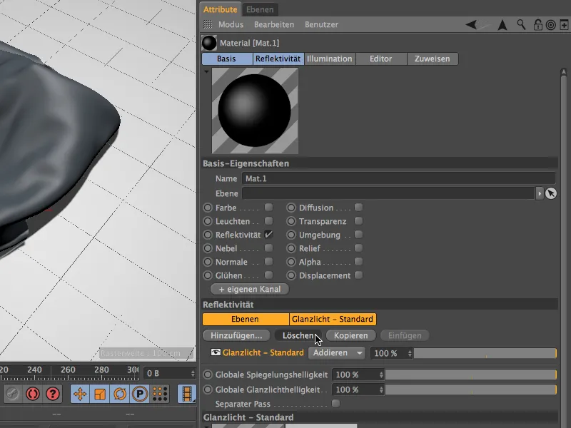
Instead, we add the Irawan layer (woven textiles) to the reflectivity channel from the Add... menu.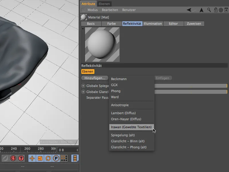
The settings dialog for the fabric layer we have just created should look familiar. Only the roughness is missing compared to the other materials we have created. Before we start selecting and designing the fabric, let's reduce the specularity a little and lower the brightness a little in Layer: Color.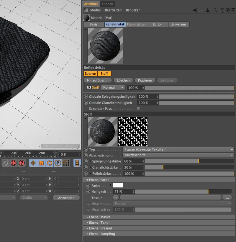
For the design of the fabric, we find a separate section Layer: Textile in the settings dialog. In addition to five common presets for different types of fabric, we also have the option of selecting the weave pattern ourselves via Custom.
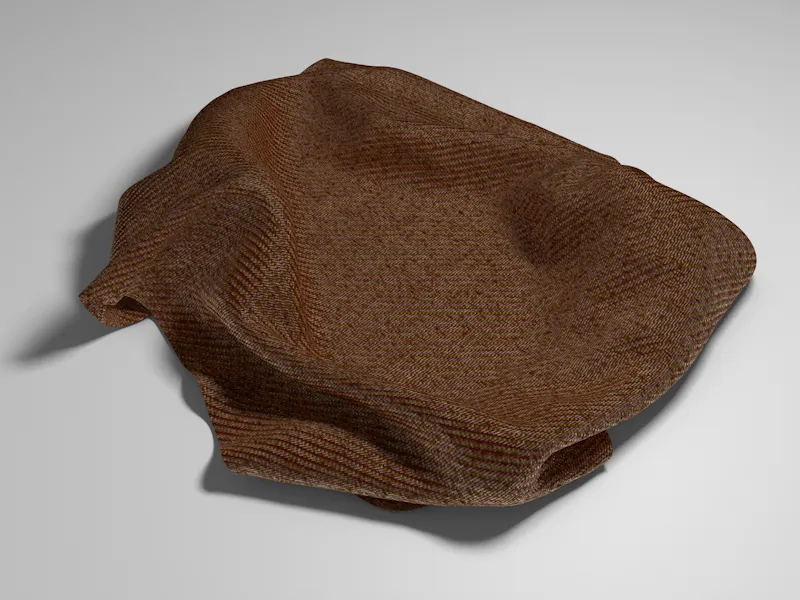
For my example, I choose a cotton fabricwith the Twill weave pattern. As you can see, there are several other weave patterns available that you should definitely try out.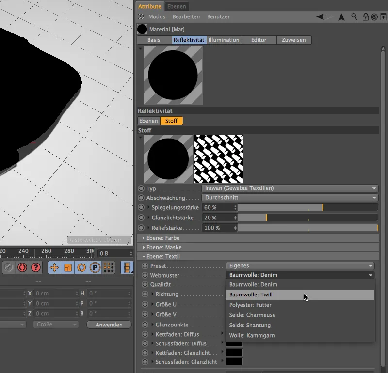
If we open the settings dialog a little further, we find a large number of parameters for defining our fabric. It is particularly important to select the correct size of the weave pattern in relation to the object so that a silk scarf does not look like a coarse knitted scarf. Here too, the best way to determine the right size is by test rendering.
The color (diffuse) and the highlight of the fabric can be defined in color fields for warp and weft. There are many more customization options, but the parameters covered so far are sufficient for our introduction.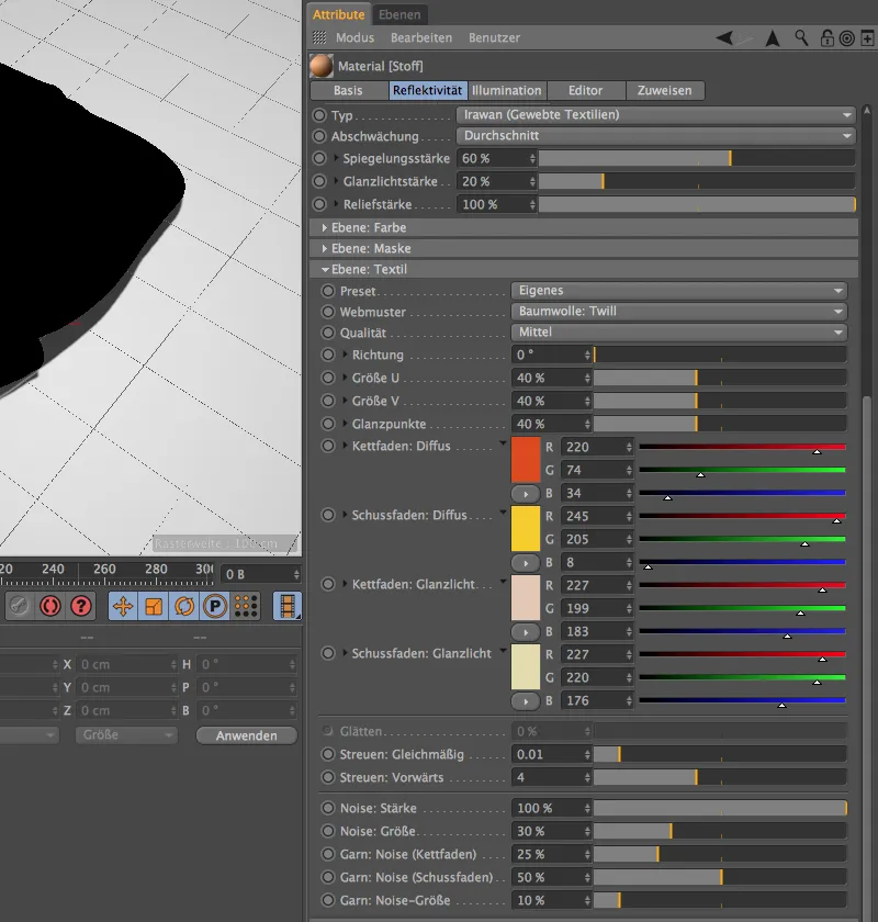
If you haven't already done so, you can now place the finished textile material on the fabric polygon object and start the rendering. The textile material not only looks convincing, it even follows the shape of the cloth we have thrown down.