Let's start with a few workflow improvements that will benefit us Cinema 4D users in all variants.
Solo mode
In the palette of editing modes, we find the Solo mode, which helps to automatically hide all irrelevant elements of the scene so that we can concentrate on working on a specific object. We have the choice between displaying only individual objects (single) or an object including its subordinate objects (hierarchy).
The object selected at the initial point in time is always used as the starting point for setting the solo mode. However, we can also use the additional Selection option to regulate the visibility automatically.
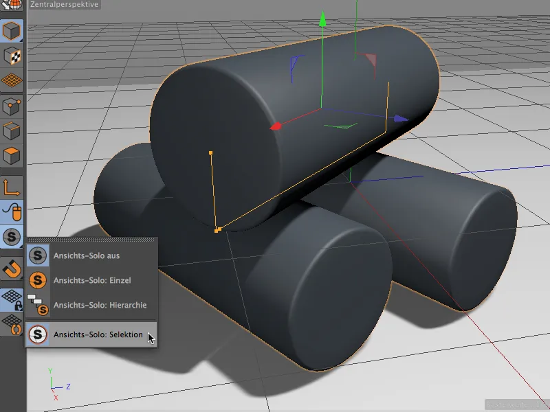
Here is a small example to illustrate this. The upper cylinder in our small scene has the two lower cylinders in the Object Manager as sub-objects. The parent cylinder is currently selected.
Outside this hierarchy, there is a scene group with a floor and light object.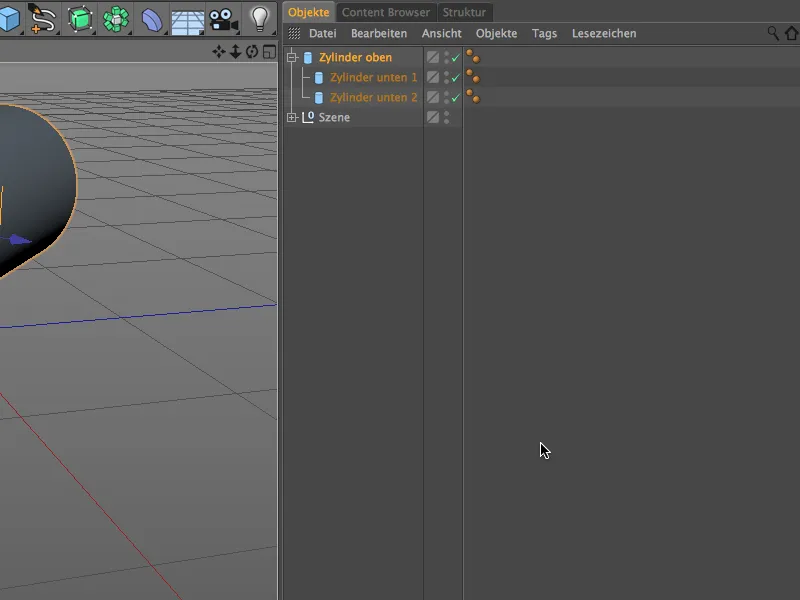
In single solo mode, we therefore only see the top cylinder . In addition to the hierarchically subordinate cylinders, the other elements of the scene groupare also invisible.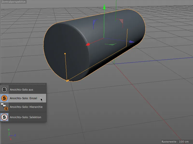
In Hierarchy solo mode, we can therefore also see the two subordinate cylinders. The Scene object group is still hidden.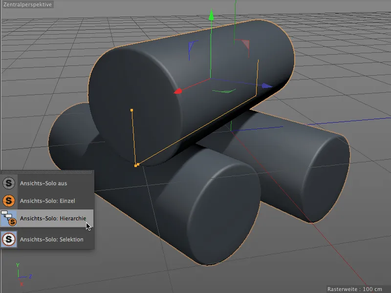
Simpler keyframe creation
Keyframe creationin Cinema 4D has never been "difficult", but now a simple click on the keyframe buttonis enough to create a keyframe at the current time. A click on an existing keyframe is enough to delete it.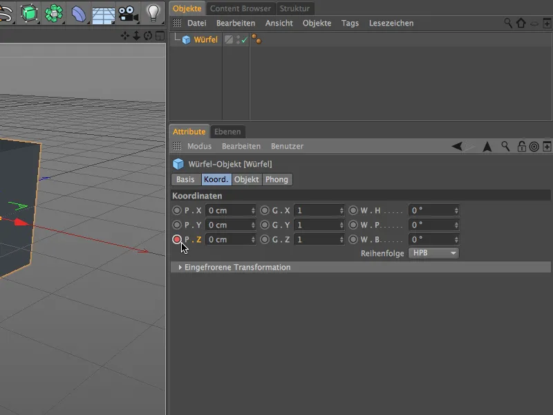
The keyframe buttonstill tells us, but with a slightly more concise display, whether an animation track already exists for this parameter (red circle) or whether parameters have been changed but not yet saved as a keyframe (orange circle).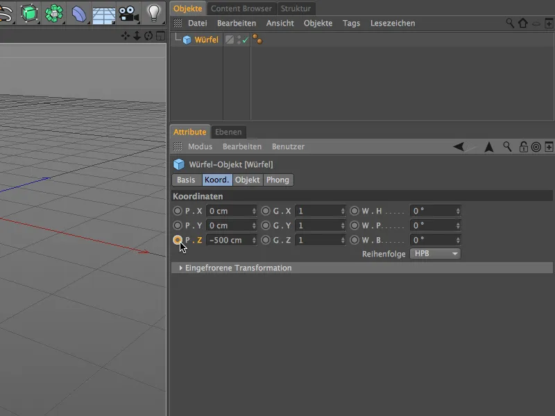
If you don't like this new way of creating keyframes, you can get the familiar "old" functionality back via the program settings. There you will find the option Keyframe buttons (old) under Timeline/Function graph for the attribute manager.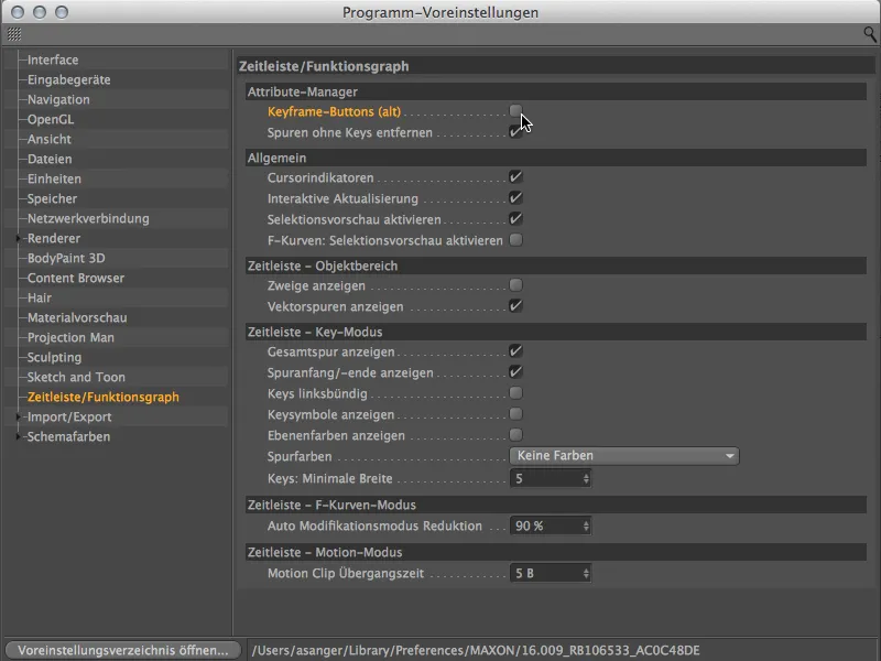
Improved symmetry object
In version 16, the symmetry object offers some very useful new functions that make it easier to work on the symmetrical model without being disturbed. For better clarity, let's take a look at the model of an alien built using the symmetry object. The right-hand side can be selected and modified, while the left-hand side only exists as a mirror image of the symmetry axis.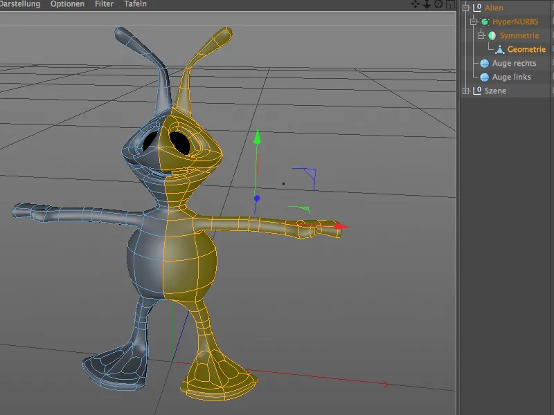
In the settings dialog of the symmetry object, some additional options are available especially for modeling. Using Keep points on axis, we can now ensure that no points lying on the symmetry axis are inadvertently moved. Delete polygons on axis prevents polygons from moving beyond the axis during modifications and causing problems.
The Flip button swaps the editable side of the model with the mirrored side. One click on this button is enough ...
... to easily switch sides and continue modeling on the other side.
Of course, you have also noticed the Automatically flip option above. If we activate this option ...
... we no longer have to flip the symmetry ourselves. It is done automatically as soon as we cross the symmetry axis in the view.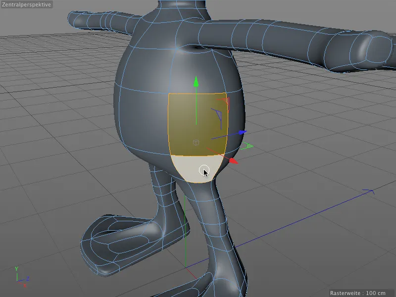
Particularly practical: When we flip the model, not only does the previously mirrored side of the model become editable, selections are also retained and are immediately available after the page change.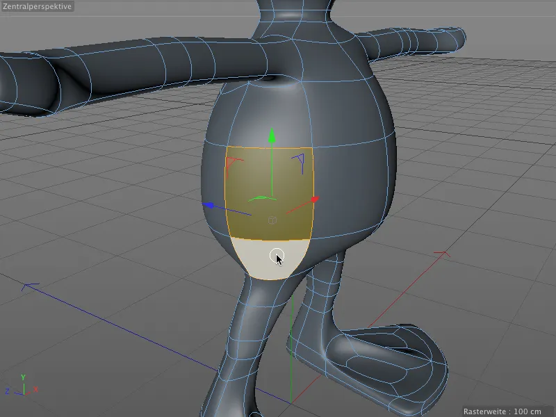
Revised gear object
The gear object, which has been enhanced with numerous additional parameters, should not be missing from our overview. If you haven't had much use for this parametric spline object so far, you might like this object due to the new application possibilities for saw blades or brake disks.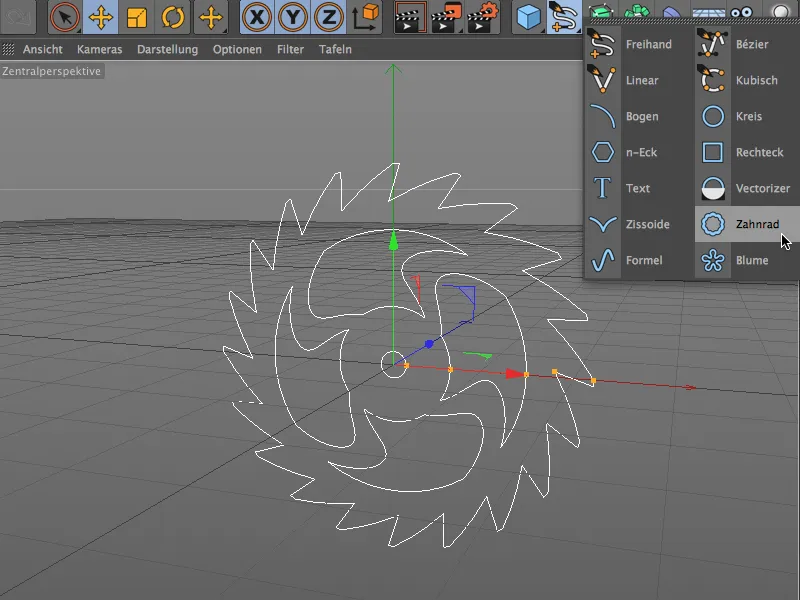
If you only need a simple gear wheel, you can activate the compatibility mode in the settings dialog of the gear wheel object and design your gear wheel with a more manageable number of parameters.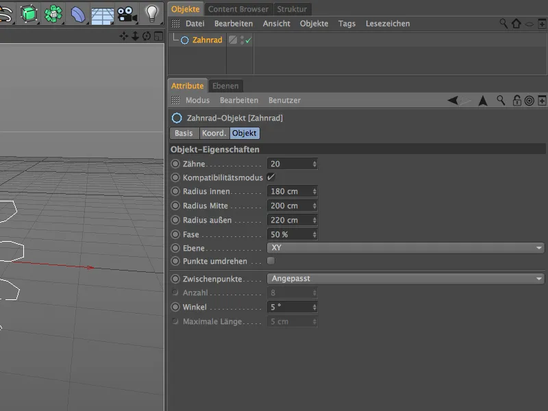
When fully equipped, the gear object offers a wealth of parameters that should leave nothing to be desired. Under Type, we first decide whether we want to keep the gear (involute), whether we want saw teeth (pawl) or a smooth rounding (flat) for all kinds of disks. The remaining parameters on the teeth sideare used to design the outer area.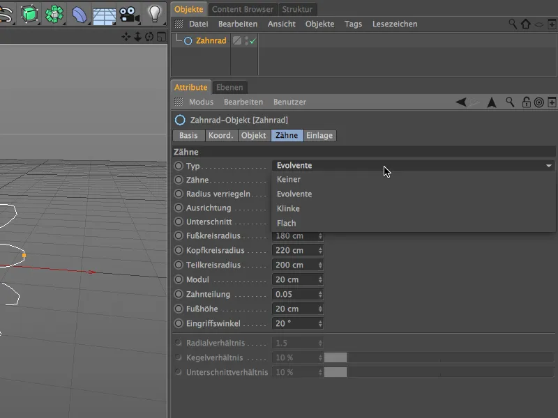
The inserts pageof the settings dialog, on the other hand, deals with the inner area of the gear object. Regardless of the teeth, we decide here via the type whether spokes, holes, arches or shafts are used in the inner area of the gear object. There are again numerous parameters available for further design.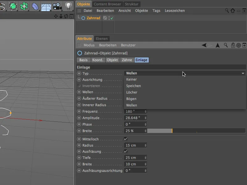
If you don't have the time or inclination to delve deeper into this matter, you can find a lot of cogwheel objects in the Content Browser under Prime>3D Objects>Cogwheel Objects as illustrative material and for immediate use.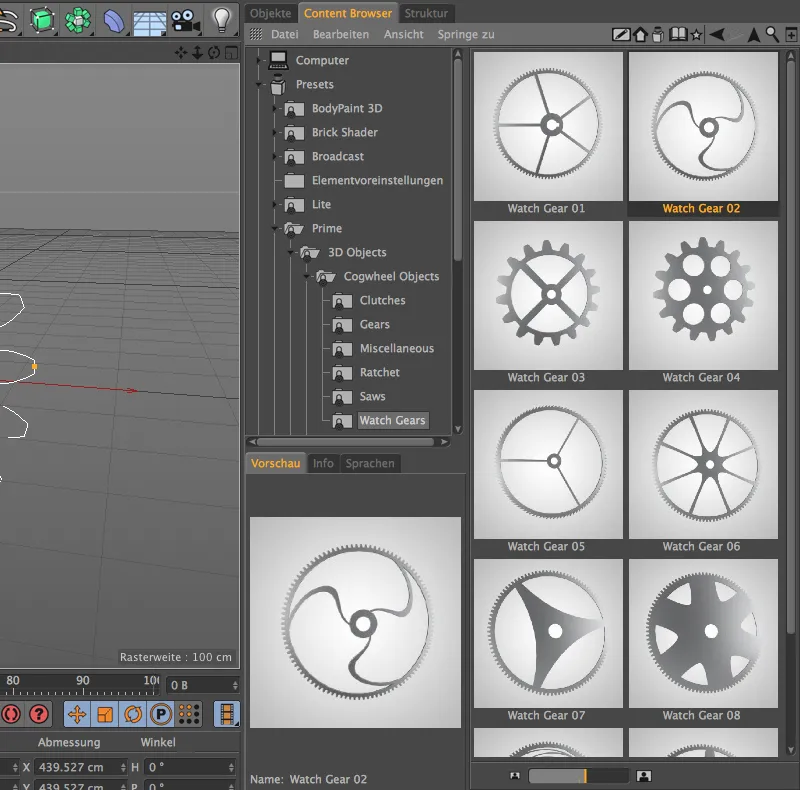
Mesh check
When modeling in Cinema 4D, there are many opportunities for accidental modeling errors in the heat of the moment. Unfortunately, you usually only become aware of such errors in the mesh at a much later stage.
To prevent these unpleasant situations, version 16 offers a very convenient way of checking the model for any modeling errors with the mesh check. Want an example? How many problem areas do you notice when looking at this polygonal cylinder?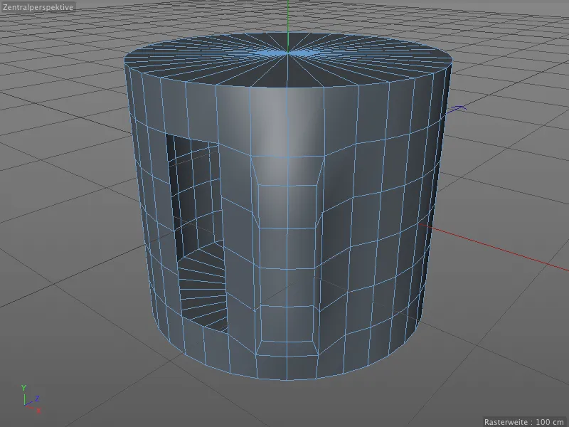
Let's simply ask the Cinema 4D mesh check. To do this, we switch to the Modeling setting in the Attribute Manager via the Mode menu.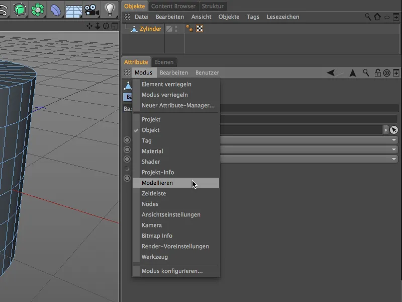
The mesh check has its own tab in the modeling settings. After activating the mesh check via the option of the same name, we can define which problem areas should be displayed in color in the editor.
It is advisable to protect this attribute manager contentfrom changes using the lock icon in the top right-hand corner while making the necessary optimizations to the mesh.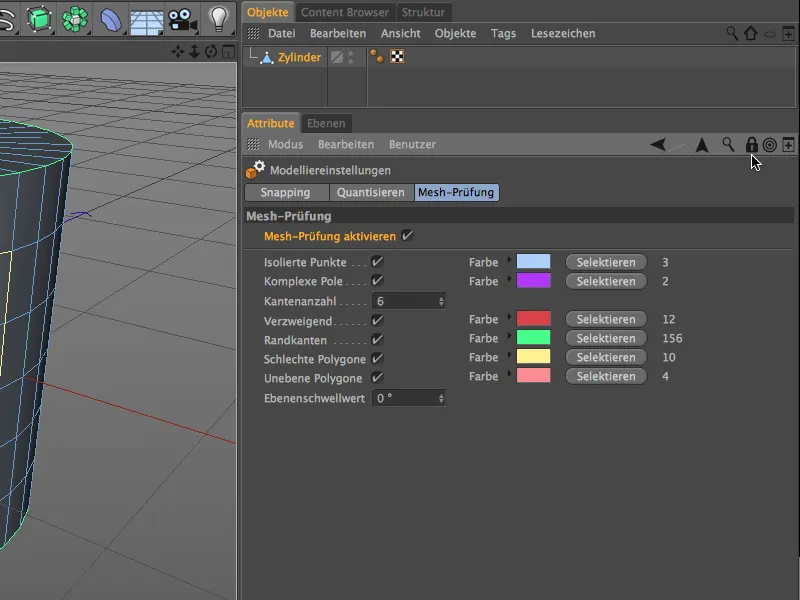
- Isolated points (light blue) can occur, for example, if we delete polygons but not the associated points.
- Complex poles (purple) are points that are part of more than 5 polygons. Smoothing problems are particularly common here.
- Branching (red) tells us that the colored edges are part of other polygons behind them.
- Boundary edges (green) are polygons that are part of only one polygon. This is also true for the top surface, which is separate and not connected to the rest of the cylinder.
- Bad polygons (yellow) are, for example, polygons that are duplicated in congruence. An accidental extrusion with a 0m offset is sufficient for this.
- Uneven poly gons (pink) are polygons whose points do not lie on the same plane. This is not unusual for four-sided polygons and is usually solved by subdivision or smoothing using subdivision surfaces.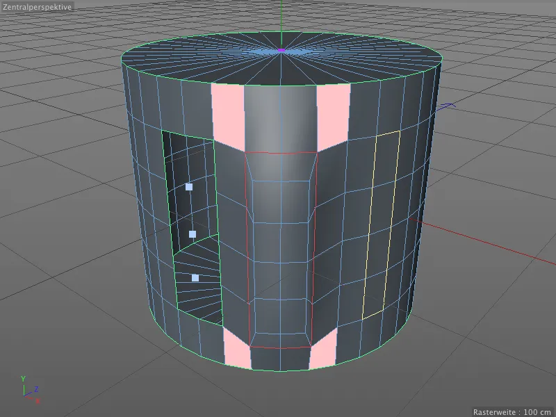
Let's take a quick look at what lies behind the branched polygon edges. If we delete the front row of the extrusion at the front of the cylinder, we can see that the edges marked in red are actually part of a third polygon planebehind it.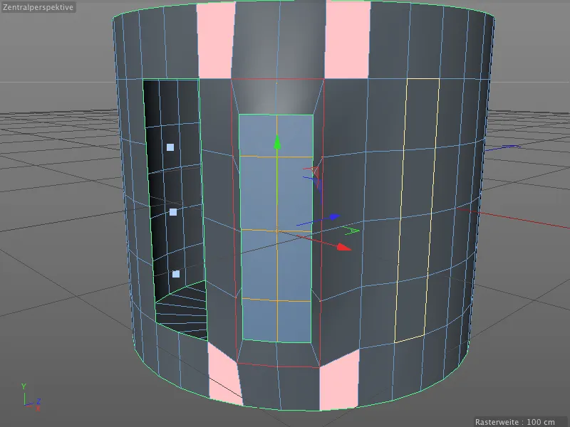
The mesh check is not only very helpful when optimizing a polygon mesh, it can be especially useful for troubleshooting when everything seems fine in the editor view.
UV Peeler
The UV Peeler is a new, practical tool in BodyPaint 3D for adapting textures to cylindrical or tubular objects. The starting point is always one or more edge selections on a polygon object.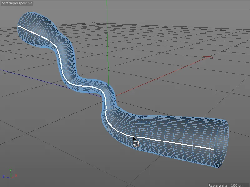
For our small application example, I have converted a sweep object into a polygon object and selected the edge row of a long side. It is not absolutely necessary to save the selection in an edge selection tag.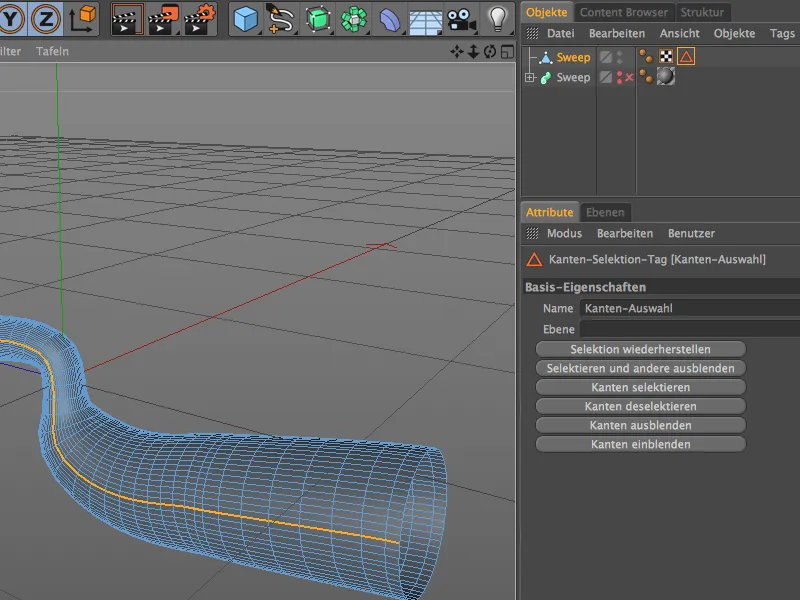
We switch to BodyPaint 3D via the BP UV Edit entry in the menu of the various layouts. There we not only have better access to the UV Peeler, but also to all the windows and managers that we need to edit a UV mesh.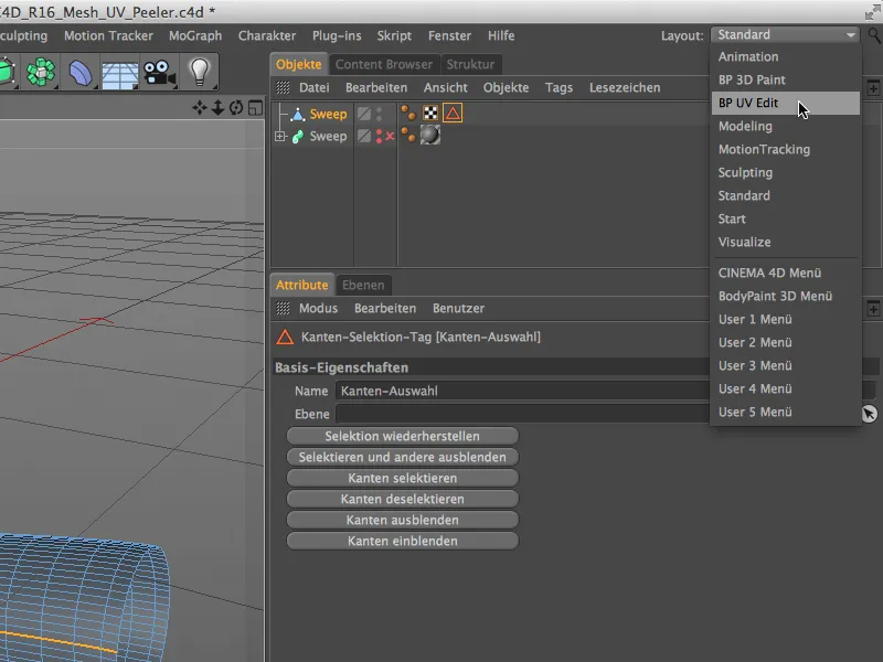
In the texture view, we can display the UV mesh of the object via the UV Mesh menu. We do not find much help with texturing the tubular object here.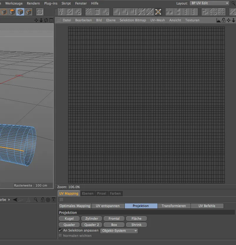
Since version 16, the UV Peeler has been available in the UV Edit menu. To call it up, an edge selection is required, which is then used to cut through the UV mesh or as a seam.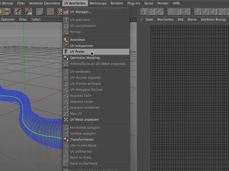
When the color of the edge selection changes to green, the editor viewindicates that it has been transferred to the UV Peeler as a seam.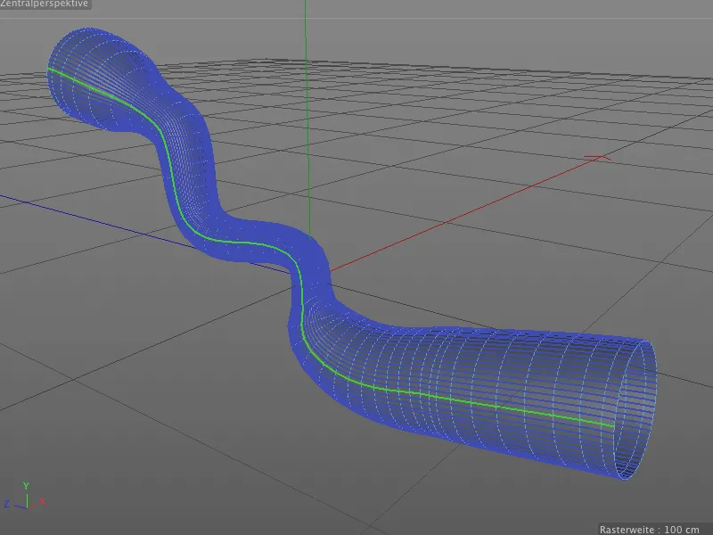
In the settings dialog of the UV Peeler tool, we can now adjust the UV grid to the actual shape using the U and V parameters. We also have parameters for scaling, inversion and handling multiple UV islands (edge selections).
This processing now offers much better orientation when texturing the tubular object.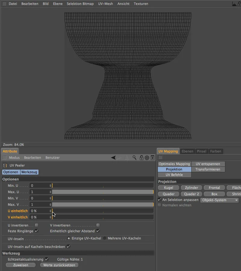
BiRender
The last new feature of version 16 that I would like to discuss in this tutorial is BiRender. Although this new feature is implemented in a somewhat unspectacular way, it eliminates a real weak point in Cinema 4D: Sketch & Toon and Hair can now render together.
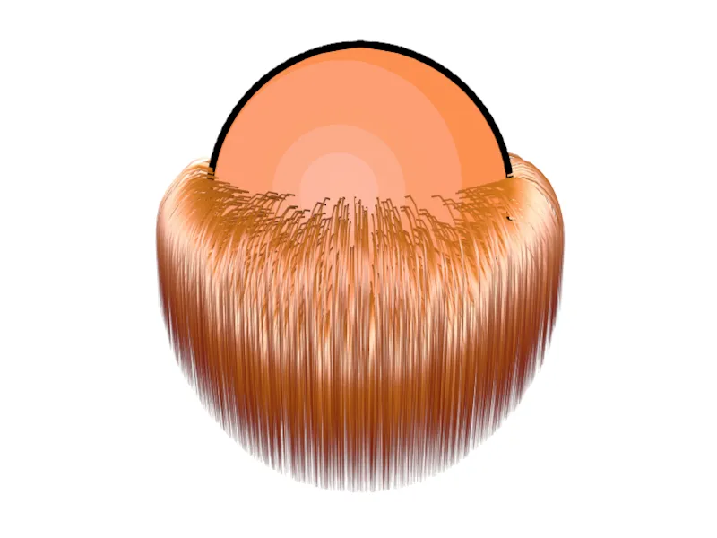
To test this, the sphere in this example has a Sketch style tag that is used to apply Sketch & Toon. As can already be seen in the editor, hair grows from a selection of the sphere, so the hair renderer is responsible for this.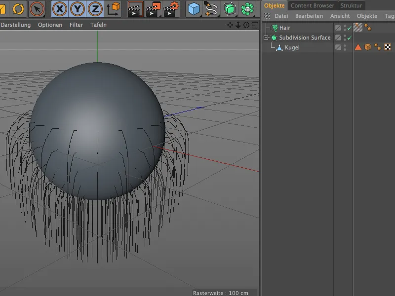
BiRender itself is not a separate area in the render presets that we need to visit. Only the Hair Renderer and the Sketch & Toon Rendererneed to be activated there, if not already done.
As a small concession to BiRender, we no longer find any fill hair in the settings dialog of the hair object. To compensate for this, the number of "real" hairs is now increased accordingly.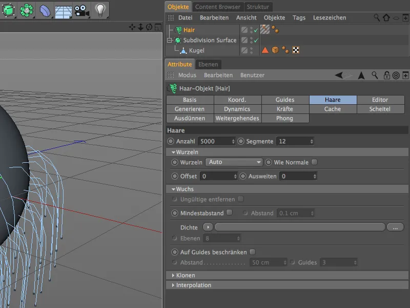
A click on the Render buttonconfirms that both renderers are working together correctly and no longer interfere with each other.