Because we are basically dealing with one more axis when working in space than in a 2D image editing program, snapping elements is of particular importance.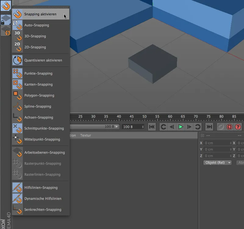
This can be seen from the prominent placement of the snapping functions in the snapping palette. All important snapping options are presented here for quick access.
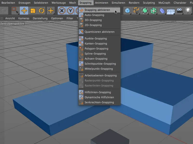
The identical list can be found in the Snapping menu. It should be said at the outset that the basic rule "as much as necessary, but as little as possible" should always be observed when snapping. If too many options are selected, the snapping function reacts over-sensitively and makes work more difficult because it is constantly snapping to components of all kinds.
Component snapping
Let's take a look at the snapping function using a simple example. In the package with the working files you will also find the project file associated with this example.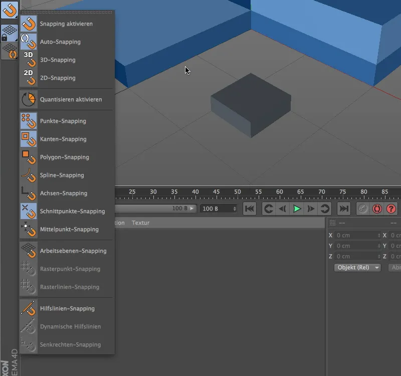
Snapping in general must first be activated via the snapping palette. While 2D snapping only reacts two-dimensionally to the elements in the current view, 3D snapping also takes into account the spatial information for snapping the elements. Auto-snapping acts as 3D snapping in the central perspective and as 2D snapping in the orthogonal views.
For this first example, the snapping function should react to points, edges and intersections.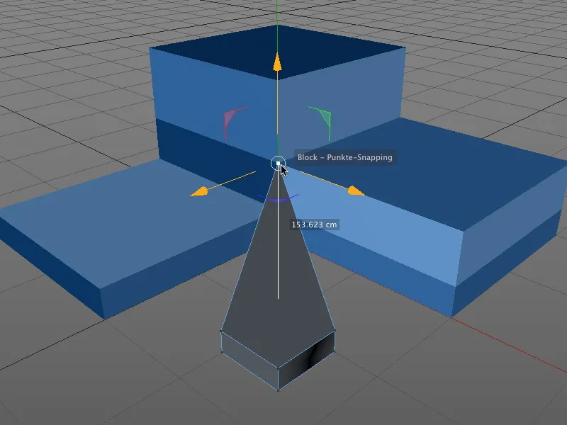
For example, if we grab and move a point of an object in point edit mode, the snapping function will ensure that the point snaps to all previously selected snapping elements. Particularly practical: the affected object and the snapping component are also displayed at the location of the action.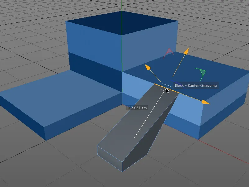
It doesn't matter which editing mode is activated for snapping. Here, an edge of the cuboid has been selected and moved to the edge of the blue object.
In model editing mode, the entire object is moved accordingly. The reference point for snapping to the components is the axis origin of the object.
Snapping with moving the axis
However, it is not always desirable for the axis origin of the object to be used as the reference point. As snapping also works with axes, it is easy to determine a reference point that is more suitable for snapping.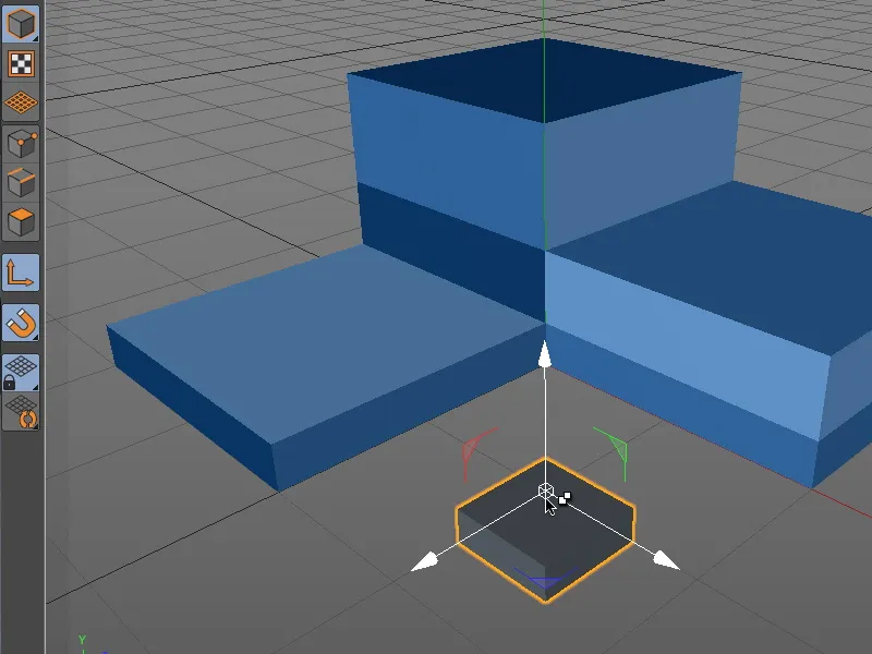
To do this, we temporarily switch to axis editing mode by holding down the "L" key and grabbing the axis origin of the object with the mouse pointer.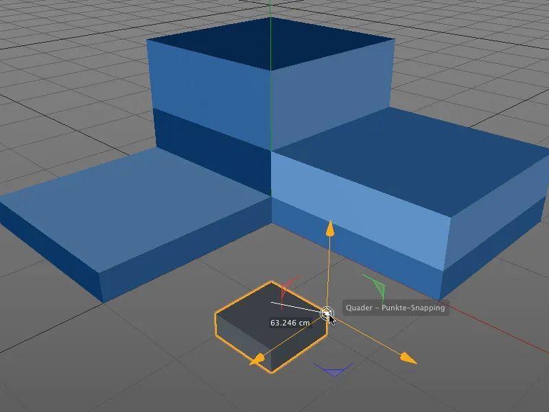
Thanks to activated snapping, the axis of the object can now be easily set to the desired new reference point, for example to the upper lateral point of the cuboid.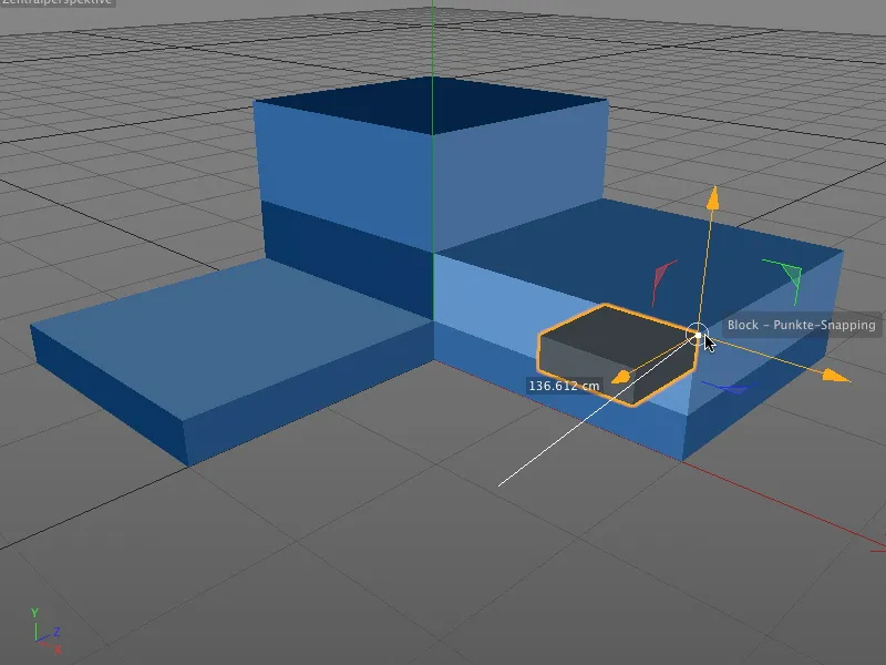
By releasing the "L" key, we jump back to the previous editing mode (in my case, the model editing mode) and can snap the entire object to any snapping component via the new reference point.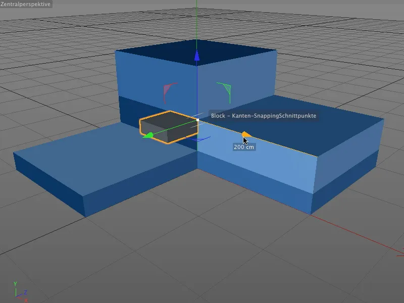
Of course, it doesn't matter whether we grab the entire object or a component it contains or whether we simply move the selected element using the axis handles - snapping works in all cases.
Snapping with dynamic guides
After these basic functions, let's take a look at the highlight of the new snapping functionality, snapping with dynamic guides.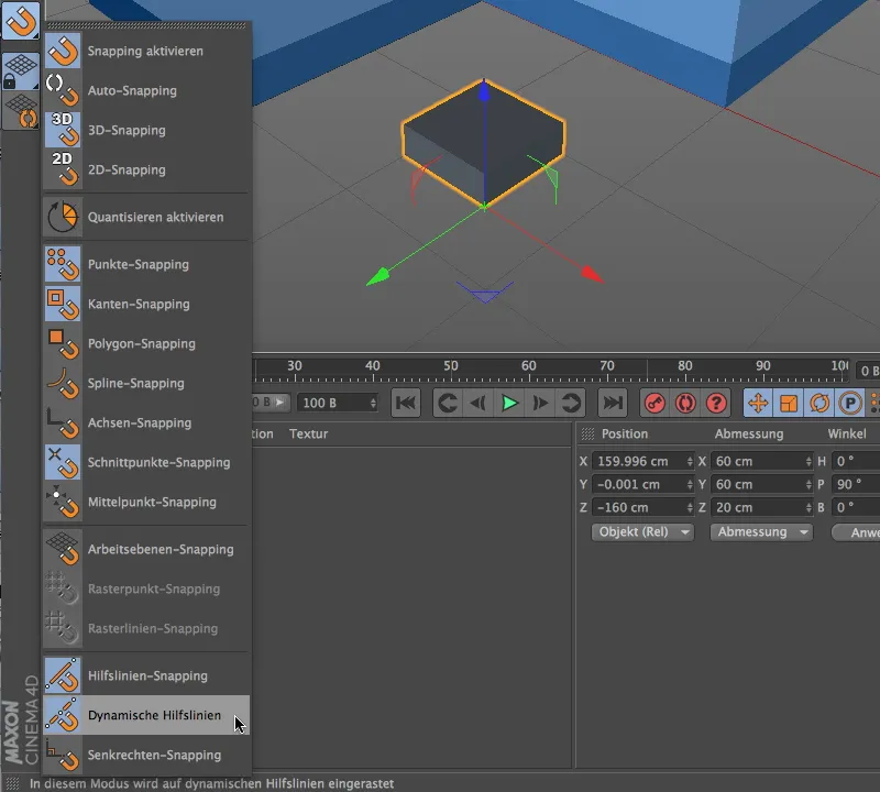
To do this, we first need to activate guide snapping via the snapping palette and then the dynamic guides.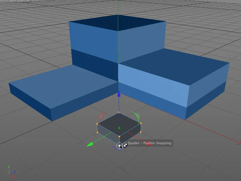
In this example, the small cuboid is to be moved to the intersection points of the outer edges of the blue block. We activate the edit points mode and select all points of the polygon cuboid. To use the lower, front point as the reference point for the offset, we grab the cuboid at this point and hold down the mouse button.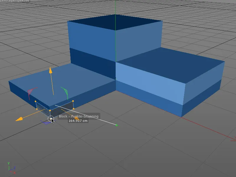
Now we create the first dynamic auxiliary line. Keeping the mouse button pressed, we drag the cuboid to the bottom corner of the block as shown in the illustration. We do not release the mouse button and remain there for about half a second in order to qualify the point as the carrier of the first dynamic auxiliary line.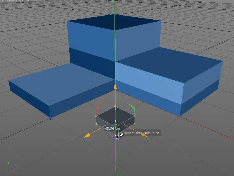
If we drag the block away from the corner again, we can see from the turquoise cross with a blue border that this first point has been set for the dynamic auxiliary line.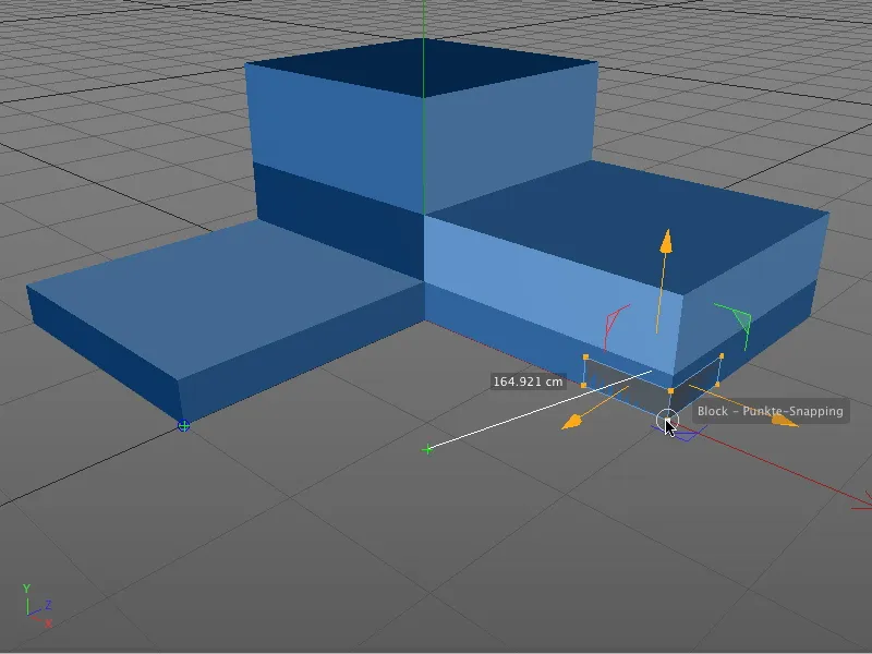
We keep the mouse button pressed and drag the front cuboid point to the bottom right corner of the blue block. Here, too, we pause briefly to qualify this corner point as a support for the second dynamic auxiliary line in the same way as on the left-hand side..webp?tutkfid=45772)
If we now move the cuboid to the intended end position, the blue and red colored dynamic auxiliary lines immediately show us where we can find the desired intersection point of the extended edges. As we have activated intersection snapping in the snapping settings, the cuboid immediately snaps into the correct position.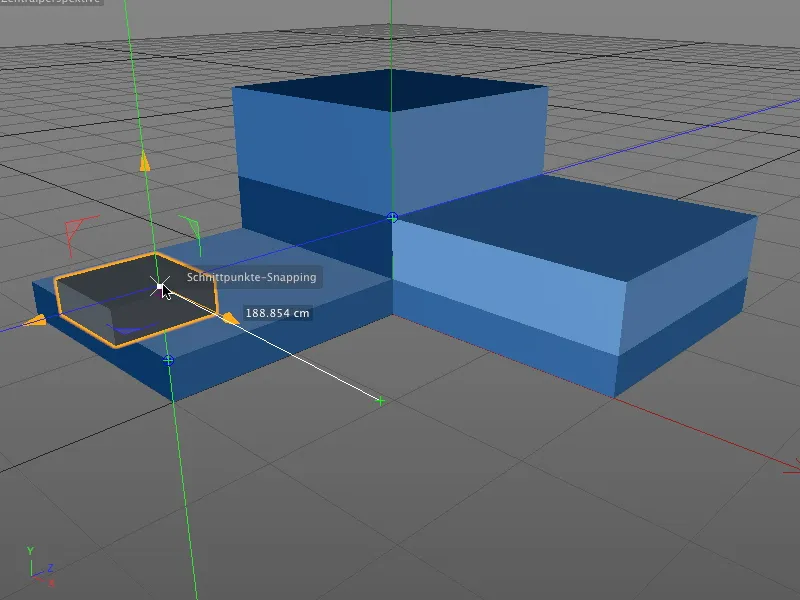
As long as snapping with dynamic guidelines is activated, we can insert any points as supports for dynamic guidelines by briefly hovering over the respective object point and aligning our snapping to them.
Snapping with other tools
The new snapping in CINEMA 4D is not only suitable for positioning objects and elements, snapping can also greatly simplify work with certain tools, such as creating polygons or the knife.
Let's take a look at another, but equally simple example.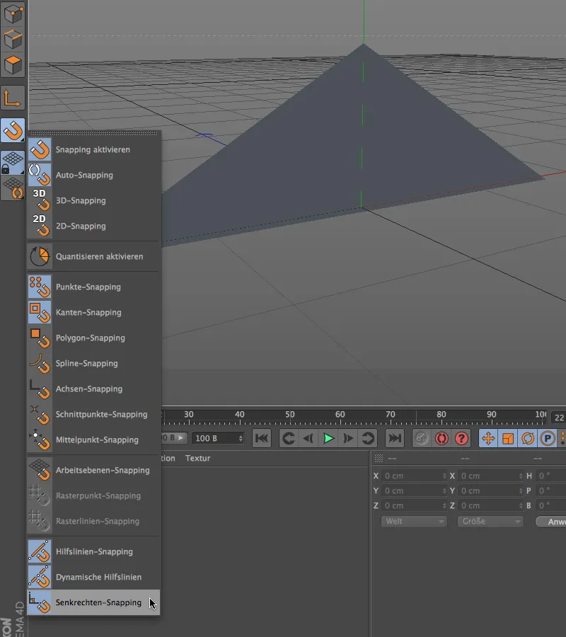
In addition to guideline snapping with dynamic guidelines, we will activate vertical snapping in order to be able to perform vertical knife cuts on a triangular polygon in the following example.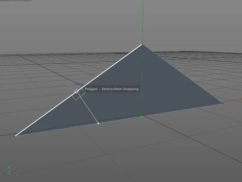
You can now start working with the knife tool. Depending on the desired position of the cut, its end point is determined using the vertical found.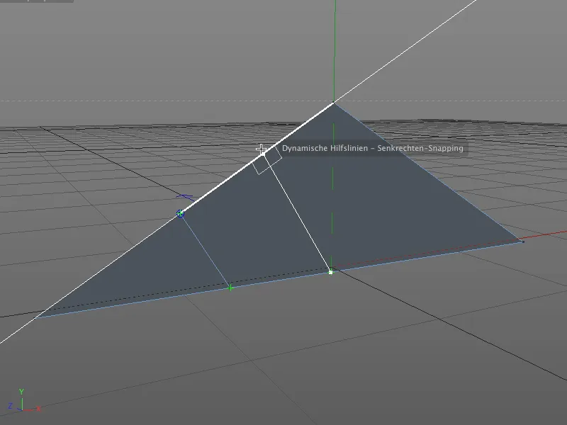
In this way, parallel cuts can easily be made on objects, as the dynamic auxiliary lines also help to determine the correct cutting position.
Quantize
Quantization in CINEMA 4D refers to the specification of increments for position, size and angle. This avoids crooked values and allows us to make interactive modifications without having to constantly check the coordinate or attribute manager to adjust the values there.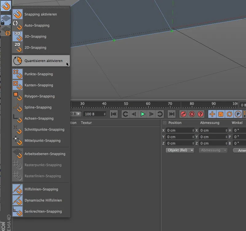
As quantization is also a type of snapping, it is also represented in the snapping palette. However, we can only switch it on or off here; the settings for the quantize function can be found elsewhere.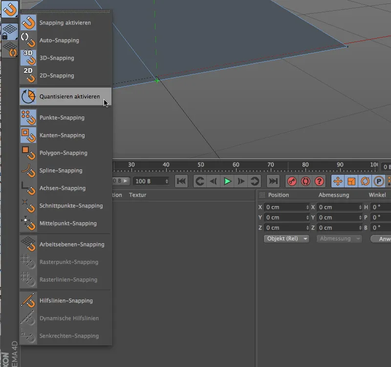
To apply the quantize function to the current working example, we first deactivate the complete guideline snapping and activate the quantization via the entry in the snapping palette.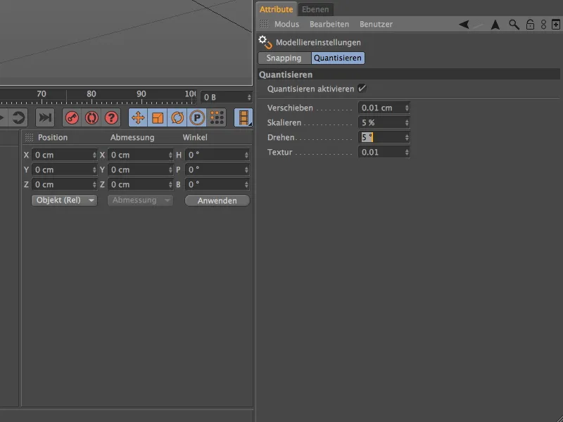
In the Attribute Manager, we find the modeling settings in the Mode menu under Modeling. In addition to the snapping settings, which we usually set via the Snapping palette, the Quantize tab provides us with the parameters for the quantize function.
In addition to the three usual step sizes for moving, scaling and rotating, we can also specify a percentage step size for the modification of textures.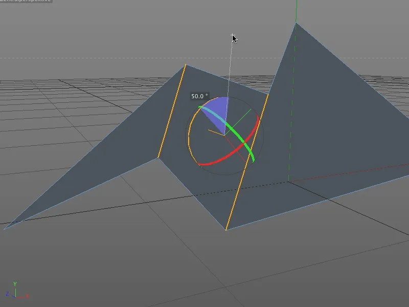
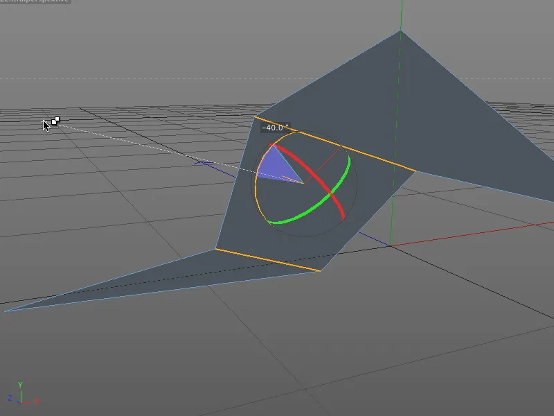
As stored in the settings dialog of the quantize function, the editing tools, such as the rotate tool, adhere to the specified step size and do not allow any changes in the positive value range ...
... nor in the negative value range do they allow crooked numbers during interactive modification in the editor.