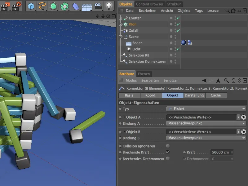
I have provided the most important scene components in the working file "PSD_C4D_R14_Konnekt_brechen_start.c4d" so that we can start building the tower and the Dynamics functionality right away.
Building the scene with Dynamics
Our initial situation consists of the first row for the tower and one of the spheres that will later be released onto the tower via a particle system. A ground object and a point light source provide a sufficient environment and illumination for this tutorial.
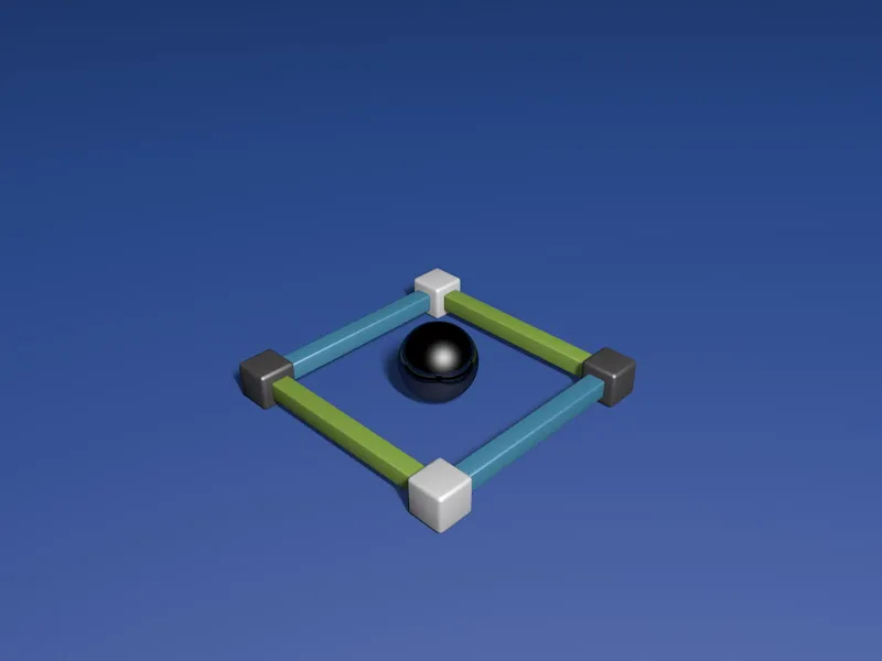
When we unfold the group of the first row, we see that its individual parts are named according to their arrangement. This will help us later when integrating and attaching the connectors.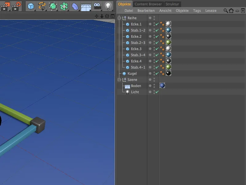
Before we pile up this first row using MoGraph, we first equip the individual elements with the necessary dynamic properties. To do this, we assign a Rigid Body Dynamics tag to the first element via the context menu using the right mouse button or via the Tags>Simulation Tags menu in the Object Manager.
You can also use this opportunity to assign this tag to all elements, but then you must ensure that you have selected all tags for the following settings.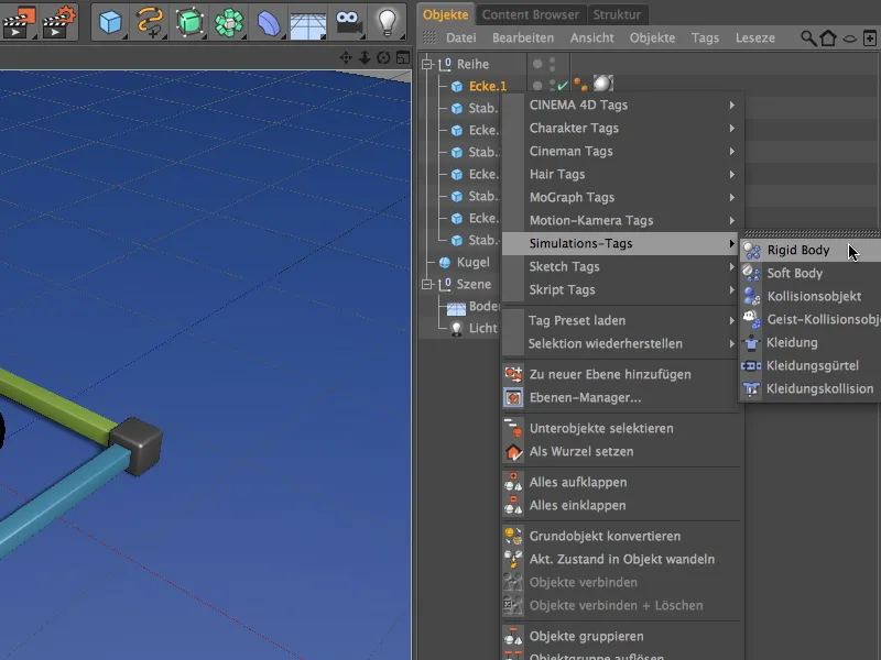
On the Dynamics page of the Rigid Dynamics Body tag settings dialog, we set the trigger to On collision so that the elements behave calmly until a collision actually occurs.
We set the speed thresholds slightly higher so that the rolling elements calm down again quickly later.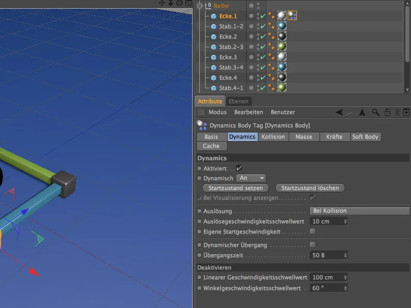
On the collision page of the settings dialog, I have used the convex hull as the collision shape. In my opinion, this setting represents an optimal compromise between collision sensitivity and accuracy for our purpose. You are welcome to experiment with other shapes. We increase the friction to 80% so that the blasted parts do not move too far away from the collapsed tower.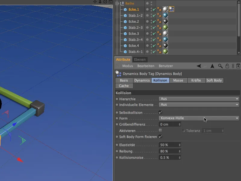
You can now duplicate the finished Rigid Dynamics body tag by dragging the tag to the other elements in the row in the Object Manager while holding down the Ctrl key.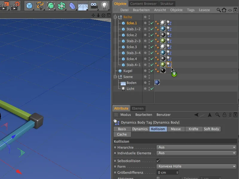
The sphere is also assigned a Rigid Body Dynamics tag. The easiest way to do this is to duplicate a tag in the row once again and adjust the parameters as follows:
We select the Immediate setting as the trigger, as the spheres should be responsible for starting the collisions. We can reset the speed thresholds to the normal values.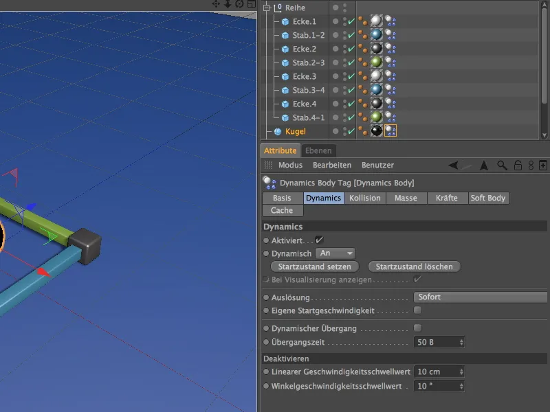
For the ball, we also reduce the friction on the collision page to 30% and set the Automatic option as the collision type. This allows the heavy ball to roll quite a bit further.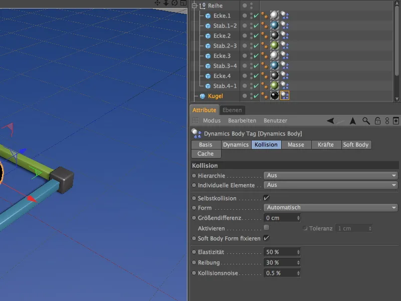
We must not forget the floor; it not only ensures that the tower stands securely, but also absorbs any falling parts. As it is a static object, it is assigned a tag as a collision object via the context menu using the right mouse button or via the Tags>Simulation Tags menu in the Object Manager.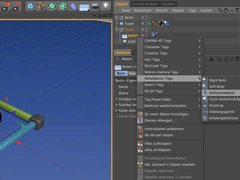
In the settings dialog of the Dynamics Body tag for the floor, we only need to increase the friction value so that the falling parts can also implement their increased friction. We can leave all other parameters at their default values.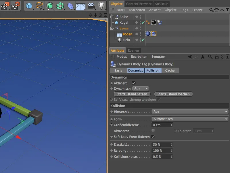
To be able to easily select and modify the tags of the tower components for later experiments, you can select them and save them in a selection object for quick access using the command Select>Selection Filter>Create Selection Object.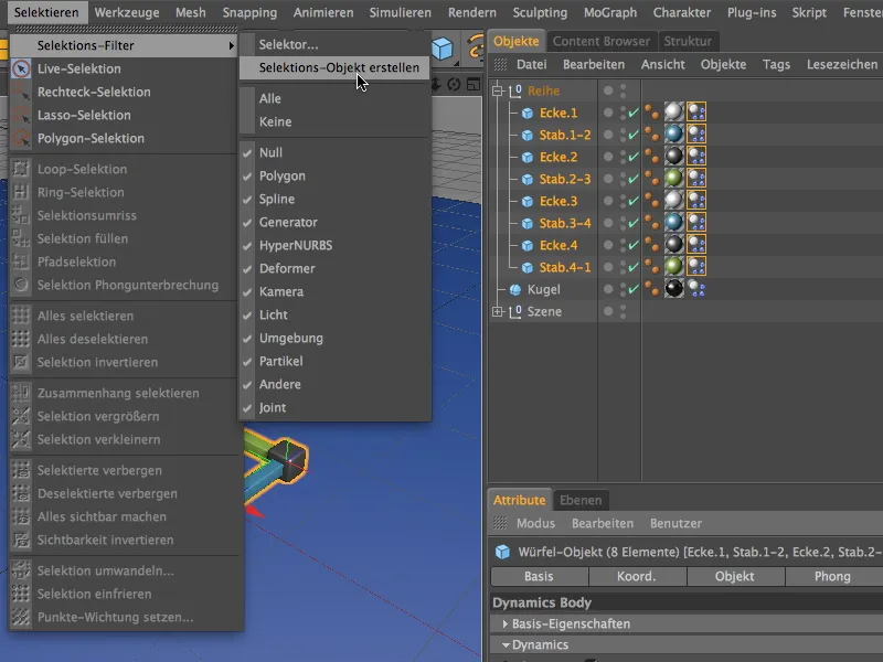
Make sure that only the Dynamics body tags are in the list and rename the selection object accordingly. To select the contained elements, simply double-click on the icon of the selection object.
Installing and customizing the connectors
In order to firmly connect the corners and bars of our component series, we need to install a connector for each connection point. Let's get the first connector from the Simulate>Dynamics menu.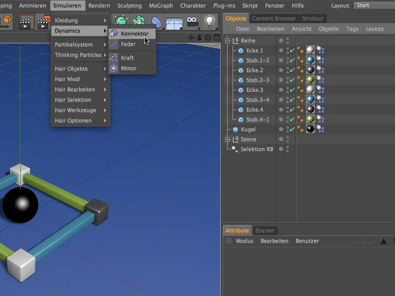
In the Object Manager, we place the first connector in the correct position in the hierarchy for a better overview, namely between the first corner, Corner.1 and the first bar, Bar.1-2. In the settings dialog of the connector, we select the Fixed type as a pure connection and drag the two objects to be connected as objects A and B into the fields provided for this purpose.
To ensure that the connection is released when a certain force is applied, we activate the Breaking force option and assign a value of 50000 cm for Force as the limit, for example. You can of course experiment with this value later.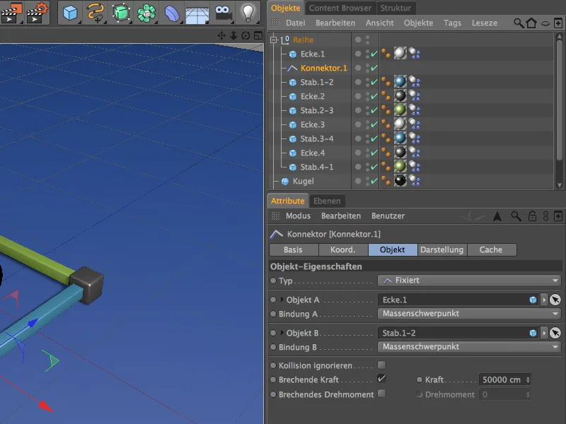
We now duplicate this first connector a total of seven times by moving it to the position between the corners and bars intended for the connection while holding down the Ctrl key in the Object Manager. The eighth connector is finally connected to the first corner to fasten the row all the way around.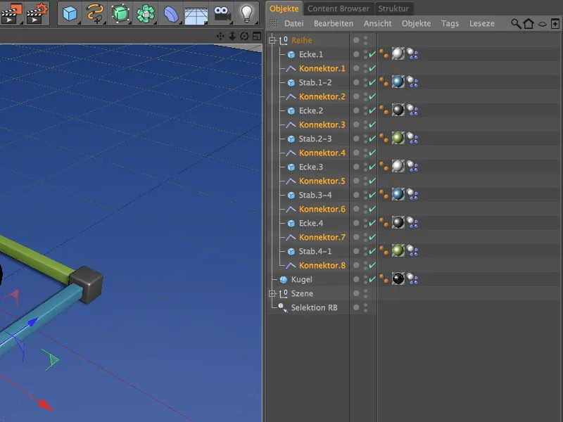
Now comes some hard work, because the other duplicated connectors still have to be assigned the correct connection objects. After all, we only have to adjust the Object A and B fields, as all other parameters remain the same.
The second connector therefore takes care of the connection between bar.1-2 and corner.2,...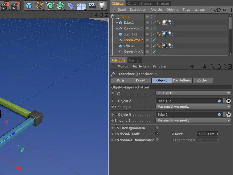
... the third connector takes care of the connection between corner.2 and bar .2-3,...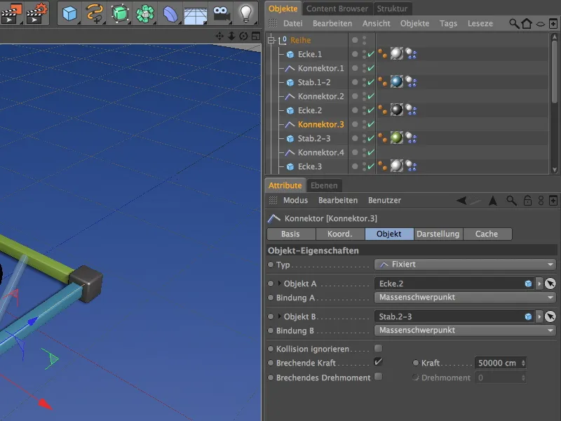
... the fourth connector takes care of the connection between rod. 2-3 and corner. 3,...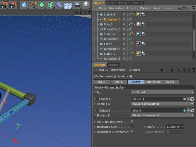
... the fifth connector around the connection between corner. 3 and rod. 3-4,...
... the sixth connector around the connection between bar. 3-4 and corner. 4,...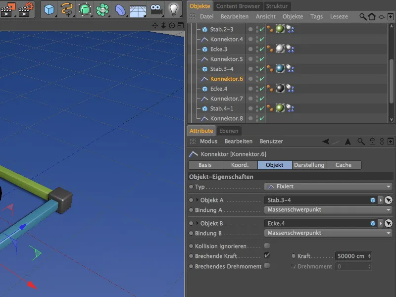
... the seventh connector around the connection between corner. 4 and bar. 4-1...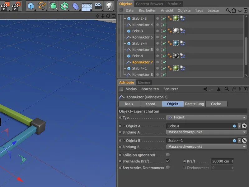
... and finally the eighth connector around the connection between bar. 4-1 and the initial corner corner.1.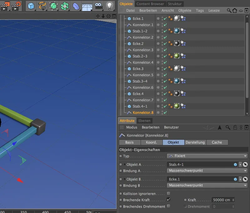
In purely functional terms, this would set up the connectors, but all connectors are still in the position of the first corner. We can correct this with a few clicks. The Apply command from the Tools>Arrange objects menu helps us to do this.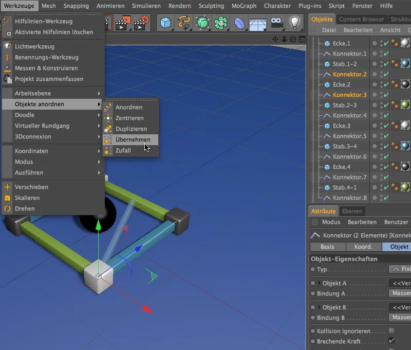
In this way, we assign corner.2 as the position to the selected connectors 2 and 3. In the settings dialog of the Apply tool, we simply drag the corner.2 into the Apply from field and click on the Assign button.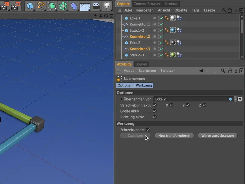
In the same way, we set connectors 4 and 5 to the position of corner. 3....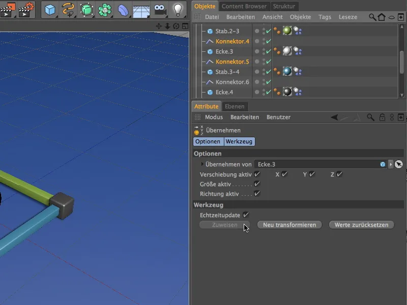
... and the connectors 6 and 7 to the position of corner. 4. The two connectors 1 and 8 are already in the position of the first corner, so we don't need to change anything here.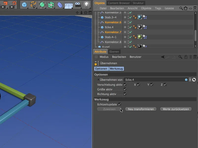
So that we can also experiment with the settings of the connectors, as already mentioned, we select all connector objects via the Object Manager and place them in a new selection object using the Create selection object command from the Select>Selection filter menu.
We also give this selection object a meaningful name and can now finally take care of building the tower with MoGraph clones.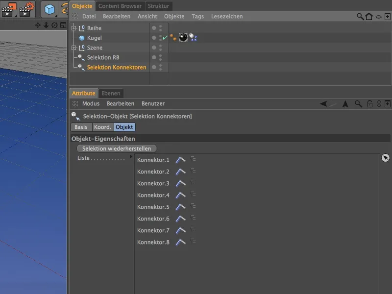
Building the tower with MoGraph
Although MoGraph is not absolutely necessary for creating the copies of the component series, it is simply much faster and gives us more freedom when readjusting.
To duplicate the row of components as a tower using clones, we get a clone object from the MoGraph menu.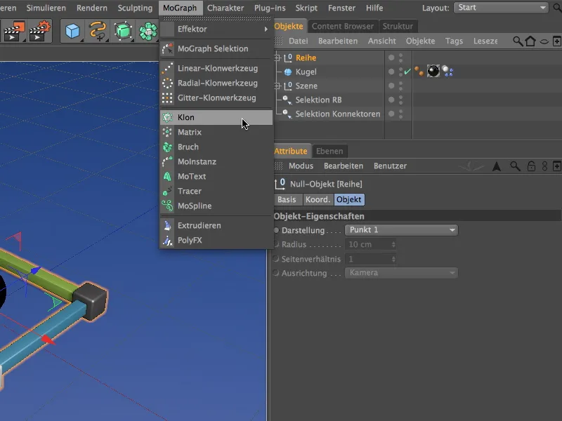
Our first row is to be cloned, so we place it as a sub-object in the clone object and take this opportunity to adjust the position of the clone object so that no corner is unintentionally stuck in the ground. On the coordinates page of the clone object, we simply need to set the Y value to 10 cm.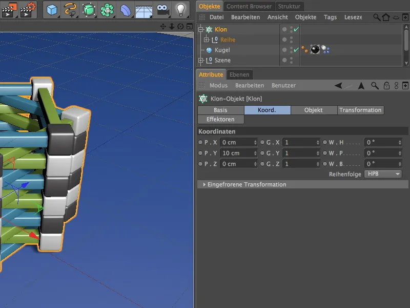
On the object page of the clone object 's settings dialog, we now enter the information for duplicating the row of components. To duplicate upwards in the Y direction, we select linear mode and an offset at P.Y of 10 cm in duplication mode per step.
We set an angle W.H of 45° so that the rows are offset and lie exactly on top of each other. I have set a total of twelve rows as the number of clones; if you want to pile up more rows of components, simply increase the number accordingly.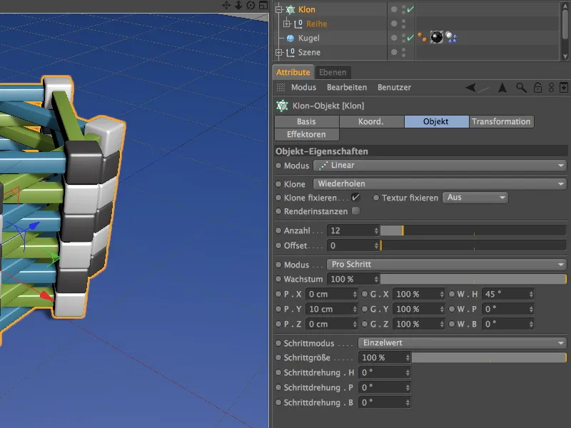
The components would then be perfectly stacked. Almost too perfect, which is why we integrate a small random offset with an effector to bring a little more randomness and therefore authenticity into the game.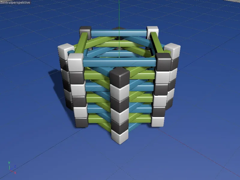
To do this, we first select our clone object in the Object Manager and then use the MoGraph>Effector menu to add a random effector to the scene. Because the clone object was initially selected, it is automatically assigned this effector.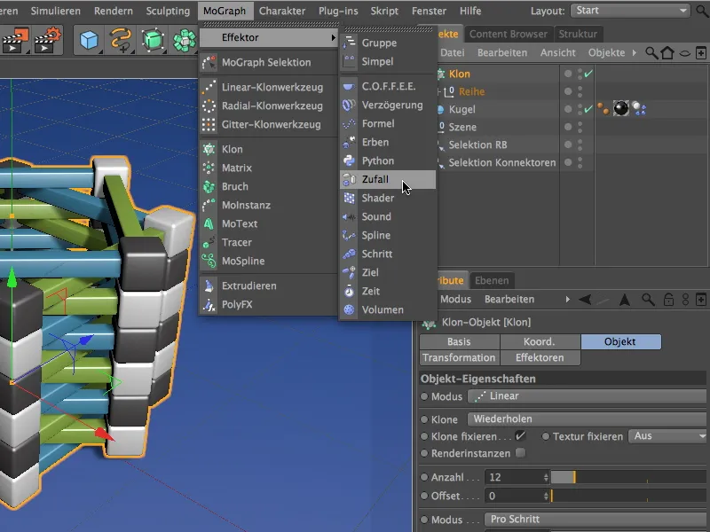
In the settings dialog of the random effector, we only activate the transformation of the angle on the parameter page. Here we assign a not too large heading angle W.H of around 3° so that the corners of the component rows still have sufficient contact area despite the offset.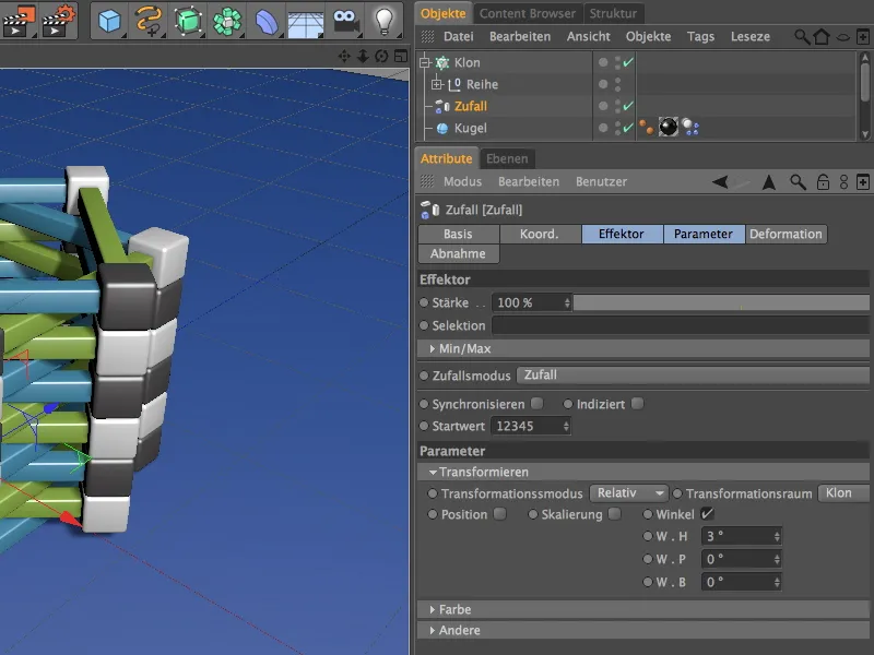
Now the tower looks much more credible. High time to unleash a few heavy bullets on our construct.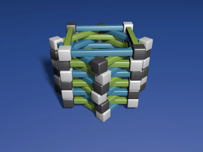
Structure of the particle system
We have already equipped the sphere object with dynamic properties, so all we have to do now is set up a small particle system to maltreat the tower with spheres.
To do this, we get an emitter from the Simulate>Particle system menu.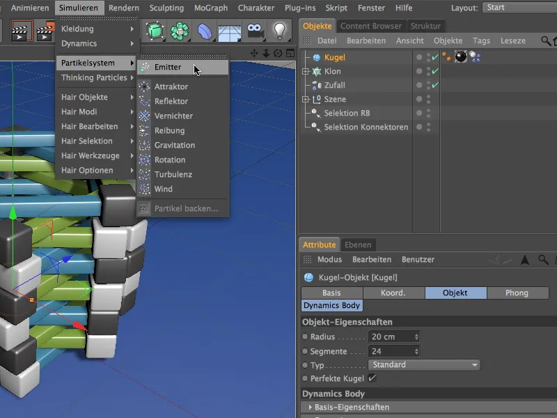
So that the sphere can act as a particle, we place it in the emitter as a sub-object via the Object Manager. To ensure that the emitter has sufficient height for the falling spheres, we move it to a height of 500 cm using its Y coordinate. As the emitter ejects its particles in the direction of the Z-axis, we must now rotate it downwards by -90° using its pitching angle W.P.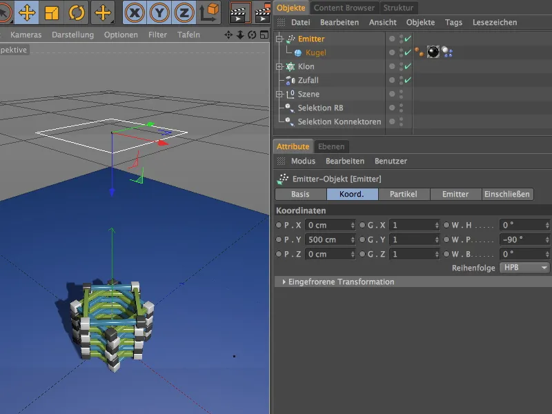
In the settings dialog of the emitter, we find all the parameters for the quantity, duration and type of emission on the particle page. I have opted for a birth rateDisplay objectsso that the spheres can also be seen as particles.
To be able to drop the particles as accurately as possible onto the tower, I set the size of the emitter on the emitter page to 180 cm each.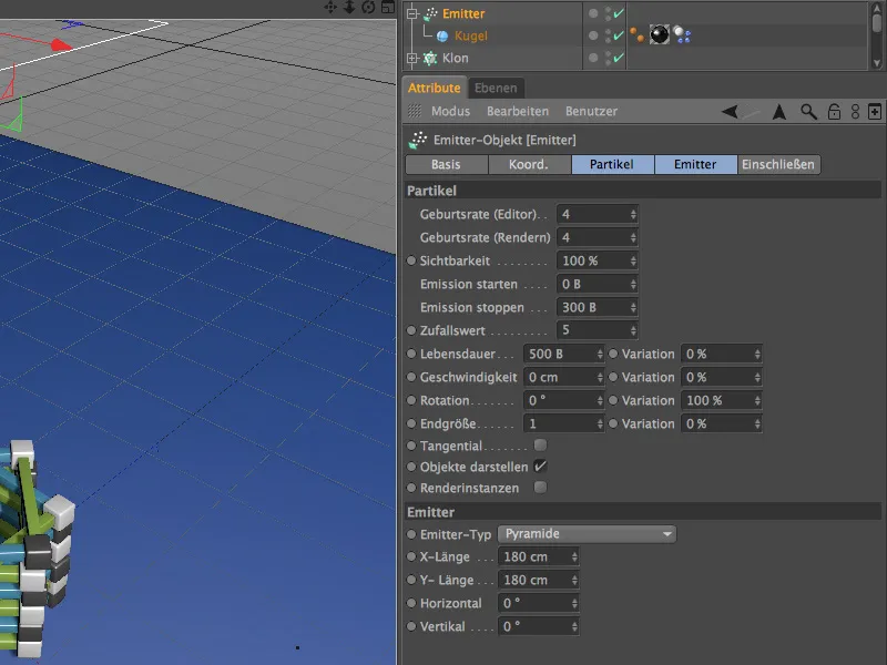
A click on the play button shows that the emitter works and, as desired, causes increasing damage to our tower.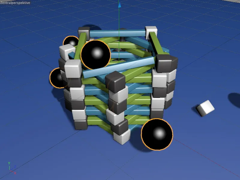
Thanks to the connectors, however, the tower does not simply collapse. All the components that were not hit with sufficient hardness or force remain connected to each other.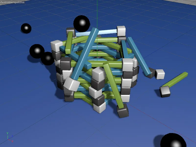
At least until the limit value stored in the connectors is not exceeded. Thanks to the selection objects we created earlier, you now have convenient options for experimenting with the dynamics parameters and, of course, the force limits.