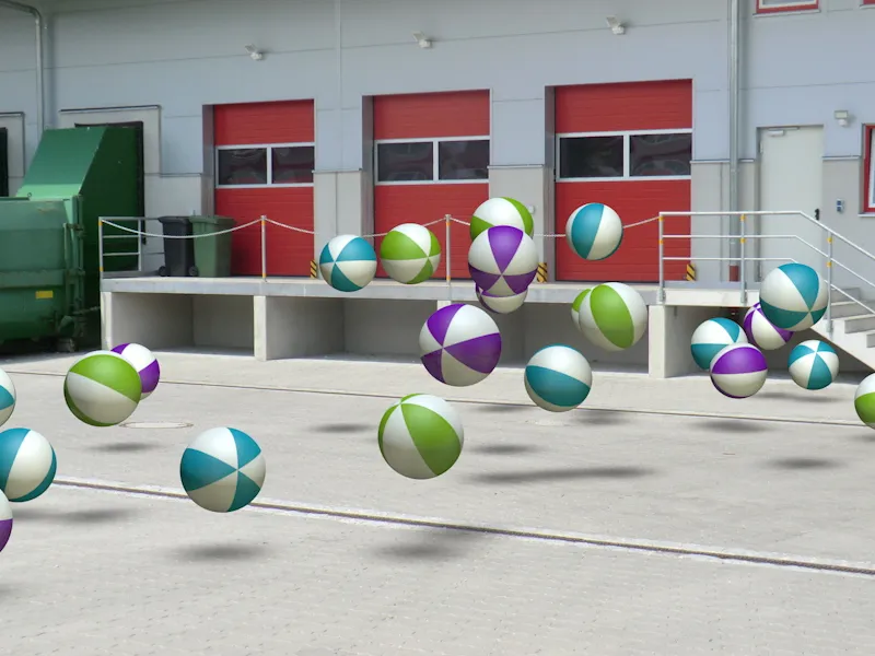
Whether for an animation or a single frame composition: the requirement to integrate 3D objects into real film or real images is increasingly in demand. Calibrating the camera in CINEMA 4D makes this easy. So that you can follow the tutorial step by step, you will find the file "PSD_C4D_R14_Kamera-Matching_start.c4d" with the initial situation in the working files.
Set-up of the scene
So that we can start setting up and adjusting the camera straight away, I have provided a small particle system in the source file, which we will later integrate into the scene created using camera matching.
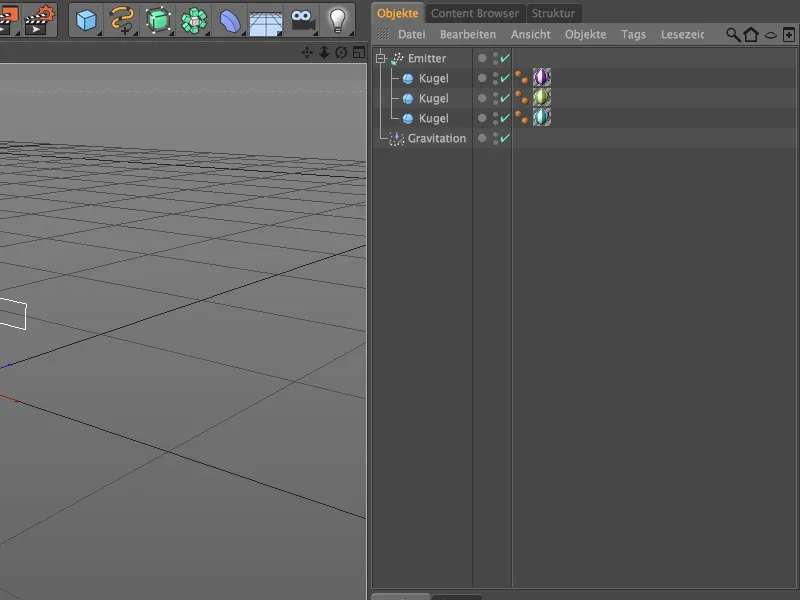
A relatively flat, but all the wider emitter generates three different colored spheres. Thanks to the integrated gravity modifier, the ball particles are not only simply ejected, ...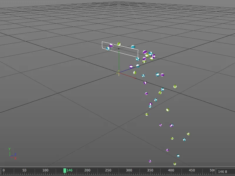
... but also fall downwards following the force of gravity, as we discover after clicking on the play button. As soon as our scene has a floor, we will also bounce the spheres.
Setting up the camera
To ensure that the balls don't get in the way during the following steps, we quickly switch the emitter to invisible using the traffic light switch in the Object Manager.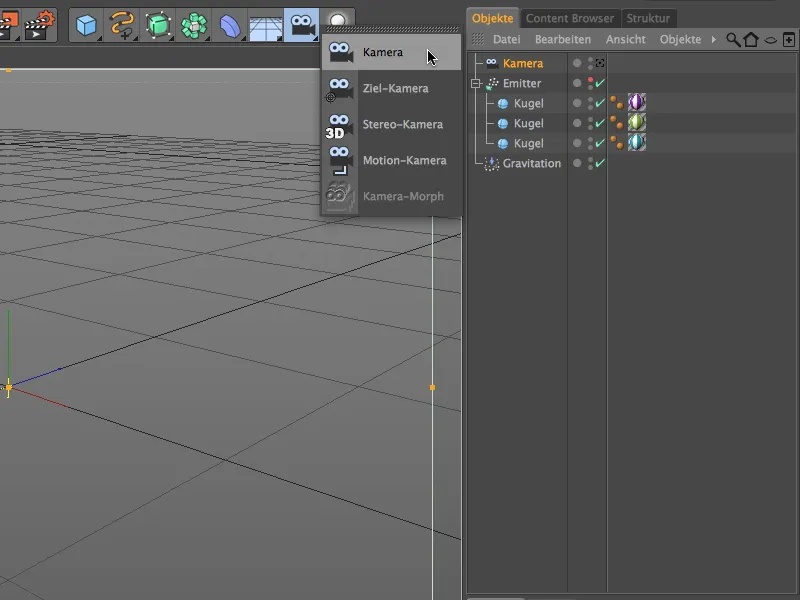
Let's start integrating the real image by creating a new camera object. This camera object adjusts itself to the photographic image material through our subsequent calibration. To give the camera the functionality for calibration, we assign a camera calibration tag to the camera object via the context menu with the right mouse button or via the Tags>CINEMA 4D Tags menu of the Object Manager.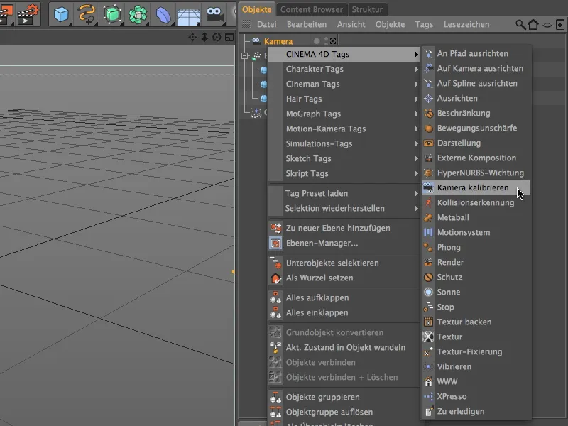
In the settings dialog of the camera calibration tag, we find the functions for loading and adjusting the image material on the image page. By now at the latest, you should have checked which aspect ratio the photo material has. We click on the button next to the Image field ...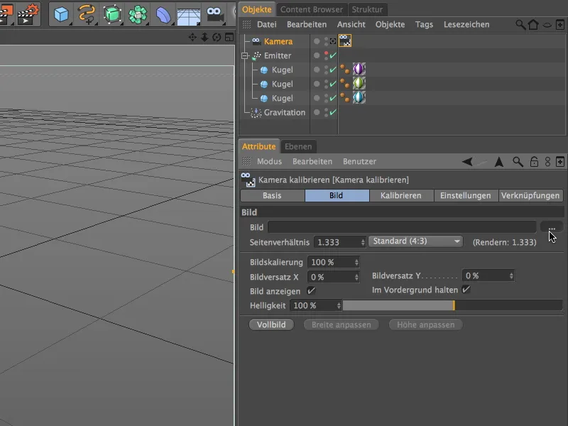
... and load the desired real image into the camera via the file open dialog. For this tutorial, I have provided the loading area of a company premises as the image file "Loading area.jpg". The metadata of the image shows the corresponding aspect ratio: 3264 x 2448 = 4:3.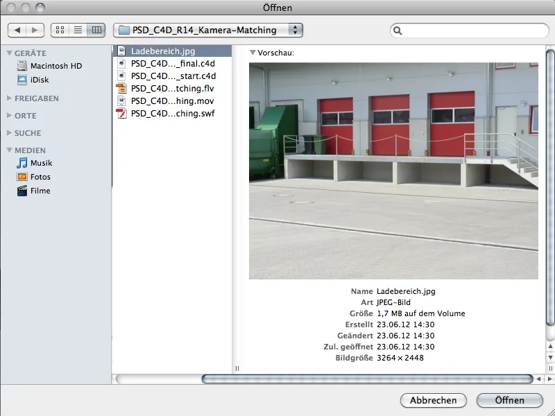
After confirming with the Open command, we find the loaded image in the viewing area of our camera.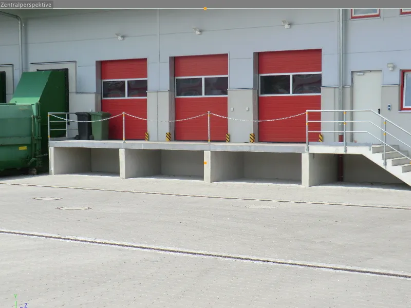
Before we start calibrating the camera to the image, we switch the camera to active (white) using the camera icon in the Object Manager.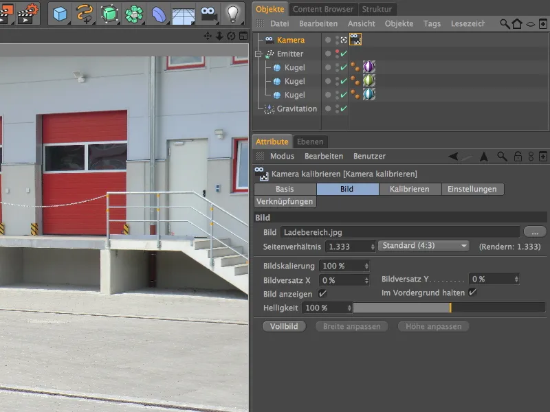
Calibrating the camera
To calibrate the camera, we switch to the Calibrate page in the settings dialog of the Calibrate camera tag.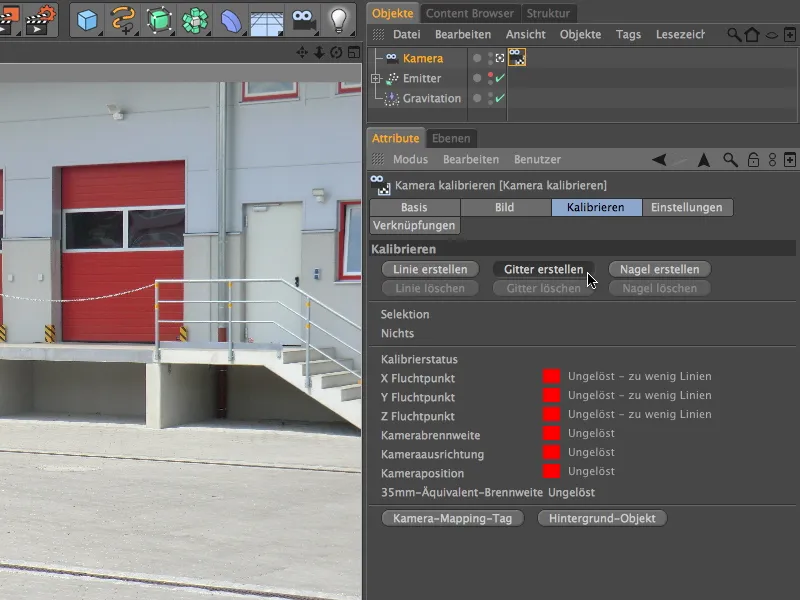
As you can see, all the traffic lights for the calibration status are still red due to a lack of vanishing points - this should now change.
Because the content of the image makes it a good idea to work with a four-sided grid rather than individual lines, we use the Create grid button to create a grid for the first step of the calibration.
With our image, it is not difficult to find lines that are "perpendicular" to each other. For the first point of the grid, it is best to use one of the corners below the ramp.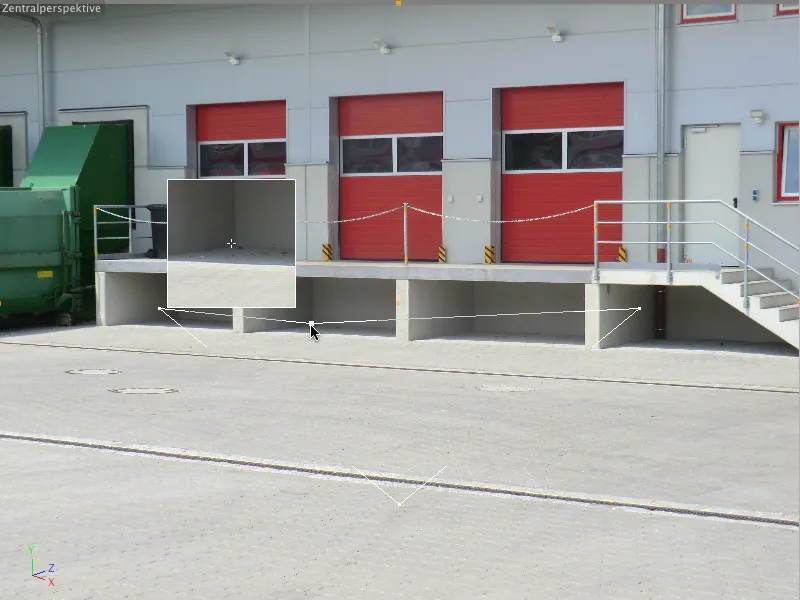
With the second point of the grid, stretch the grid as exactly "parallel" as possible to the course of the ramp edge. I have placed this corner point in the corner of the rain gutter under the ramp.
Through the third corner point, we start the edge of the grid that runs perpendicular to the first side of the grid. Use the short shoulder of the paving as a guide and move the corner point to the left until the grid line runs parallel to the concrete support of the ramp.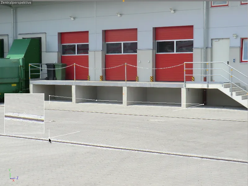
Although the position of the fourth corner point is outside the actual image, it does not pose a problem when adjusting the grid. Just make sure that the lines are exactly parallel to the edges of the concrete ramp.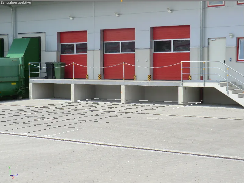
Now that the grid has been placed in the image, we need to assign the axis directions to the corresponding edges to determine the vanishing points. To do this, we place the mouse pointer on one of the grid edges and, holding down the Shift key, click on the edge until the correct axis color is available for the grid lines. In my case, the red edge of the concrete ramp defines the X-axis direction, and the blue edge defines the Z-axis direction perpendicular to it.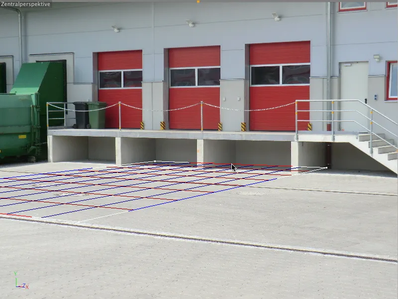
A look at the traffic light display in the settings dialog of the camera calibration tag tells us that the camera focal length and camera orientation have already been determined from the placed grid.
Using the Create line button, we now create a line to define the Y-axis.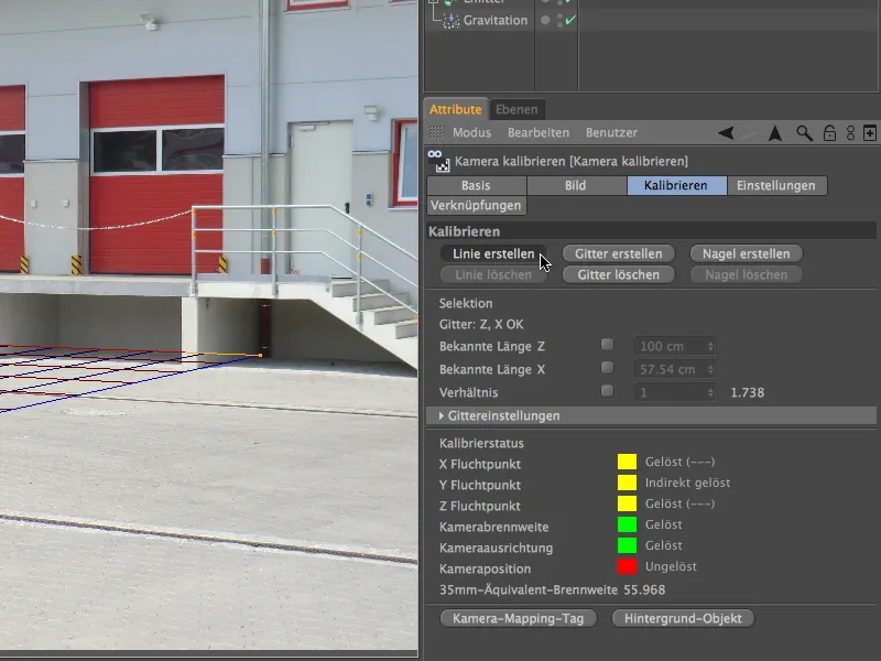
To position the line for the Y-axis, we look for an edge perpendicular to the grid - in my case the front edge of the concrete column.
We also need to specify which axis we want to define with this line. Again, by clicking while holding down the Shift key, we color the line green to define the Y-axis of the image.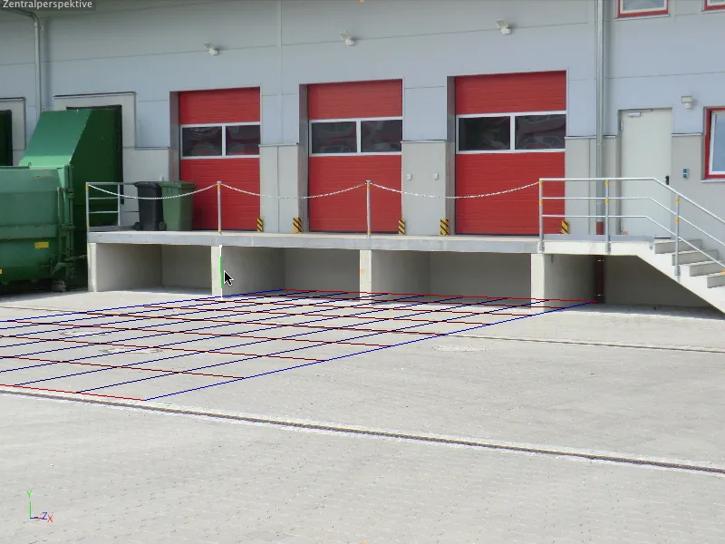
Once we have drawn all three coordinate axes in the image, the origin, the axis zero point of the scene, is still missing for reliable orientation. It is inserted into the image using a nail, which we obtain by clicking the Create nail button.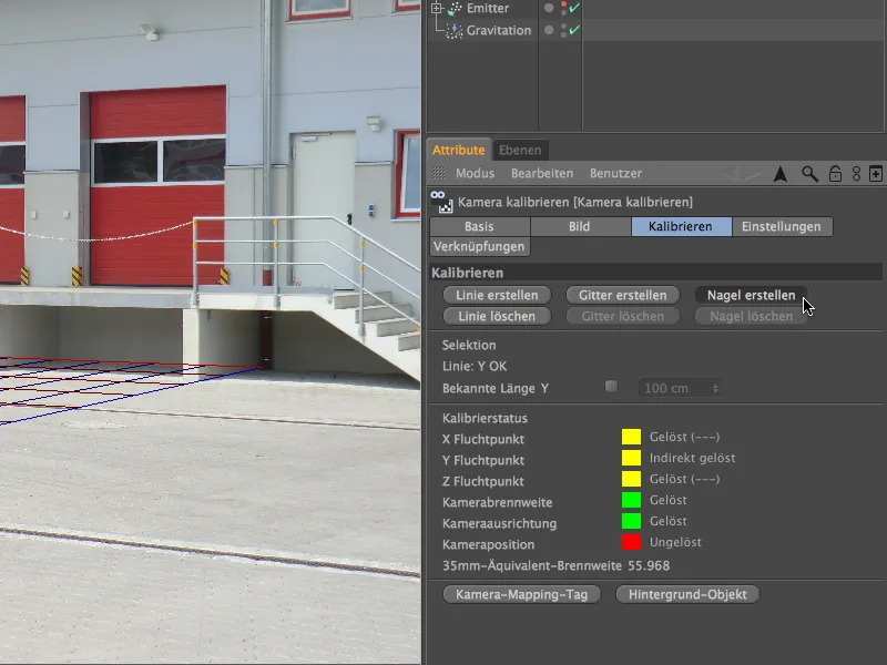
We grab the nail with the mouse and place it at the lower point of the green Y-axis line. In future, this will be the axis zero point of the scene for this camera.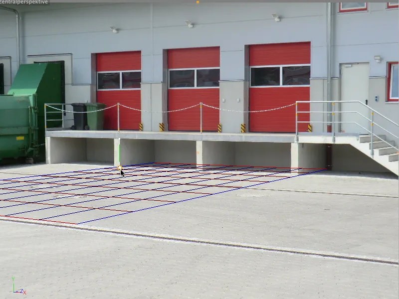
We take another look at the settings dialog of the camera calibrationtag and see that the camera position has been calculated from the vanishing point and axis information we provided. You get even more green fields with further assistance in the form of additional vanishing point lines.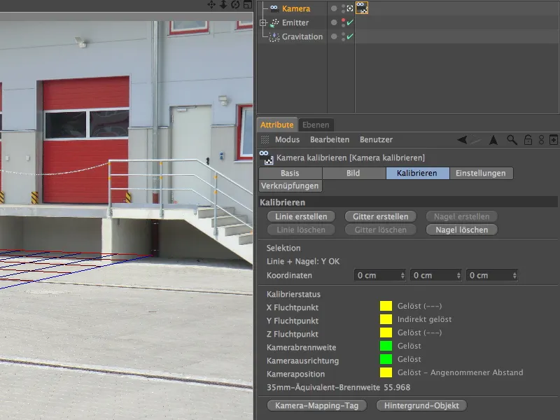
Setting up the scene
Our camera is now calibrated to the image material we have provided. Now we need to equip the scene with all the objects required for our animation.
Conveniently, the calibrate camera tag provides us with an automatic mechanism for creating a background. By clicking on the Create background button, we generate a background object with a ready-mapped background texture based on our camera image material.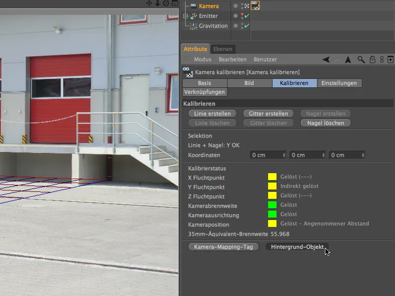
A material was created for this and placed on the background object using a texture tag. A look at the base page of the material reveals that only the color channel is used here.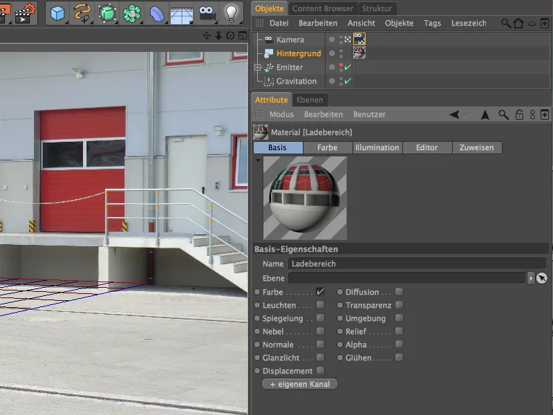
To give the balls ejected by the particle system an impact surface in the form of a floor, we bring a plane object from the basic objects palette into the scene. The familiar ground object is not suitable for our purposes because it is infinitely extended and would cause problems when casting shadows correctly.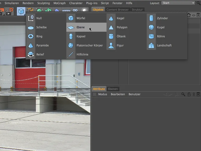
In the settings dialog of the plane object, you will find the width and depth I have estimated for the object, together with an offset of -1500 cm in the Z direction via the coordinates.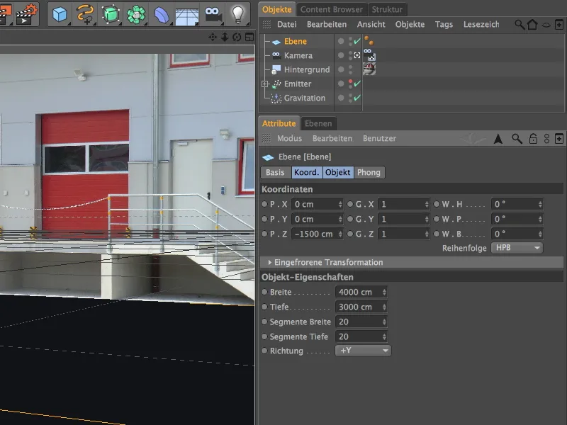
Because we only want the falling balls to cast shadows on the open area of the courtyard (anything else would destroy the three-dimensional effect), the plane should only extend to just behind the edge of the loading ramp. If necessary, simply correct this by dragging the parameter handle of the layer object.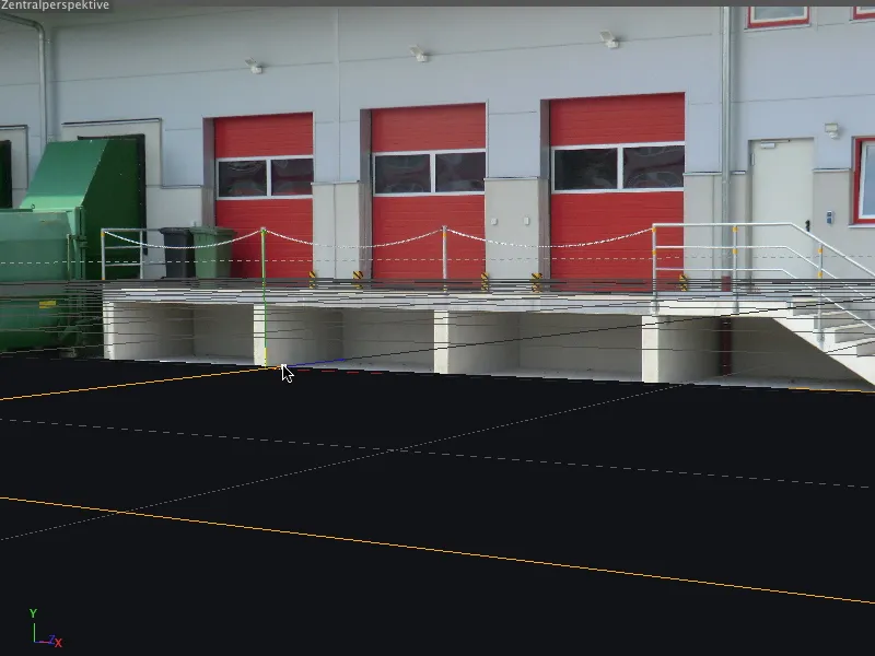
This new object integrated into the scene naturally also needs a suitable texture. To do this, we go to the settings dialog of the camera calibration tag and use the automatic function to create a camera mapping tag.
In contrast to the background object, we need the camera mapping projection type for the correct texturing of the layer object, which we can obtain using this button.
We move the new texture tag created on the camera object to the correct position in the Object Manager, of course to the layer object.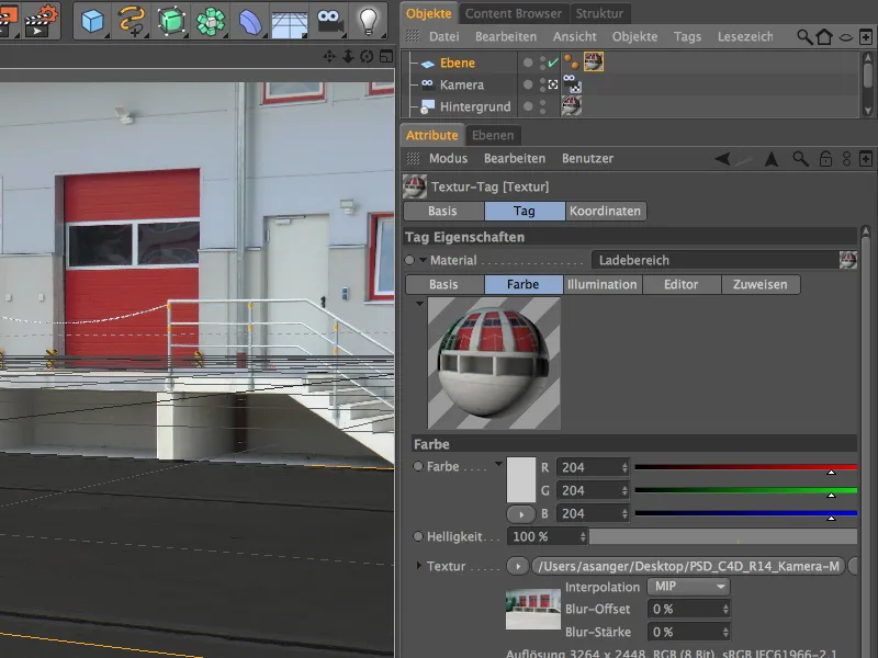
When creating the new texture tag, a new material with the texture of the loading area was also created. However, this material is unsuitable for our purposes as the texture is in the light channel and would suppress the shadows of the spheres on the floor.
We can correct this very easily by simply using the existing material (not the texture tag!) of the background object for texturing the layer object. To do this, we drag the material either directly onto the texture tag in the Object Manager or into the Material field of the texture tag in the Attribute Manager.
To ensure that the textured layer object does not have any dark shadows when the light falls on it later, we give it a render tag using the context menu with the right mouse button or via the Tags>CINEMA 4D Tags menu in the Object Manager, ...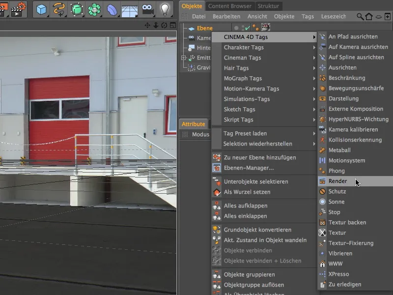
... activate the Background compositing option in the settings dialog. The layer object is now optimally integrated into the scene and behaves like an element of the real image.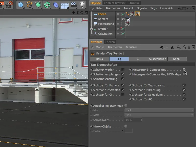
To integrate the particle system into the scene, we switch the emitter to visible using the traffic light switch in the Object Manager and temporarily deactivate the camera we have set up and calibrated. This can be done quickly via the camera icon in the Object Manager or via the Cameras menu in the Editor view.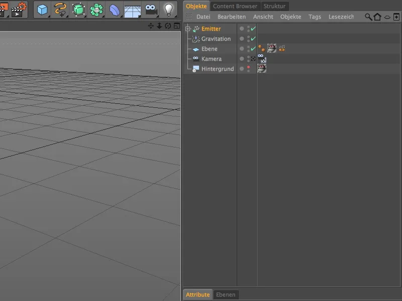
From this perspective, we can see the calibrated camera as an element of the scene for the first time and - very helpful for us - the part of the layer textured using camera matching. Using the axis handles or the values specified in the Attribute Manager, you can now align the emitter so that the spheres jump across the image area.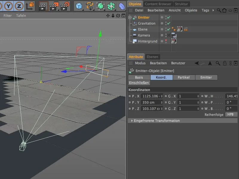
To ensure that the emitted spheres do not fall through the plane but bounce off it and continue bouncing, we set up a reflector in addition to gravity. You can find this modifier in the Simulate>Particle system menu.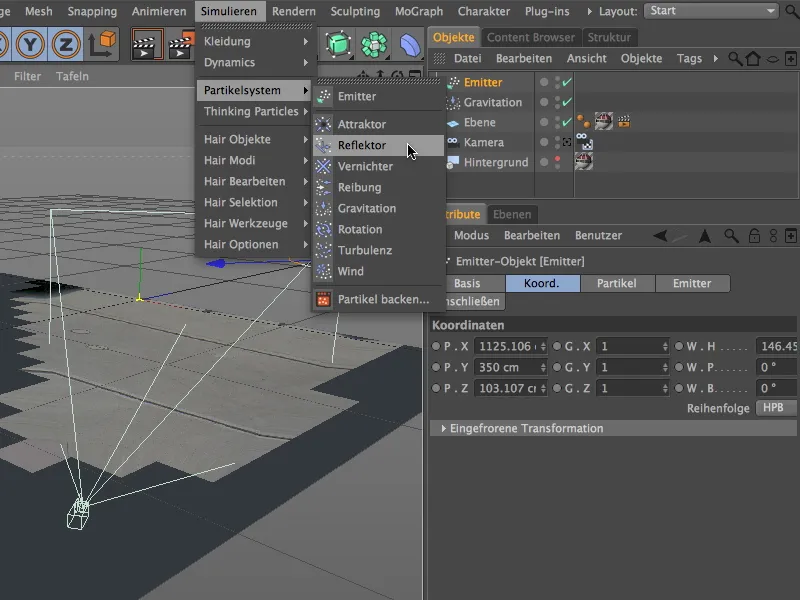
In the settings dialog of the reflector object, we set the elasticity to 70% so that the spheres are thrown back to more than two thirds of the fall height after their impact. A size of 10000 cm in the X and Y directions should be sufficient to keep all emitted spheres on the ground for the duration of the animation.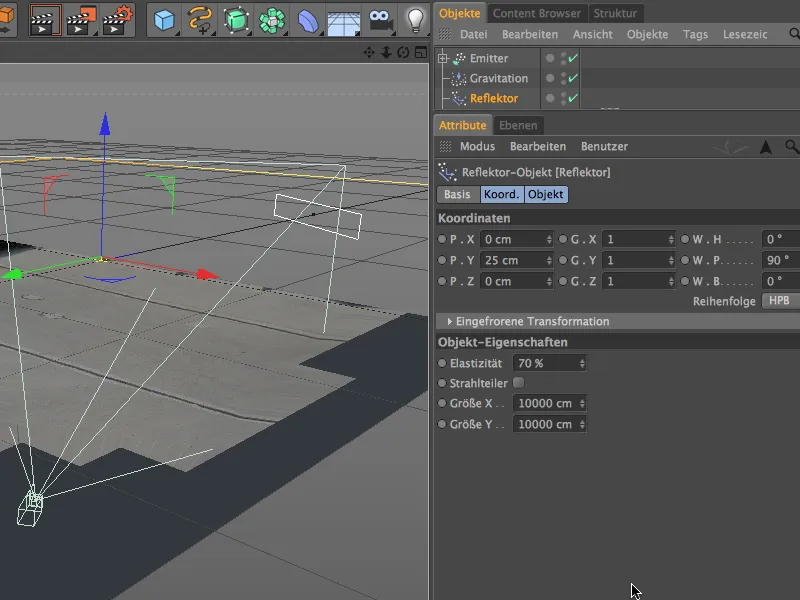
As you can see from the Y-coordinate of the reflector, the reflector plane lies just above the plane object. In our simple particle system, the center of the particle object (radius of the sphere = 30 cm) is decisive, so we need this offset. Incidentally, I have subtracted 5 cm to allow the spheres to dip slightly into the surface.
The view from the front clearly shows how the ejected spheres fall to the yellow reflector line and bounce back upwards from there.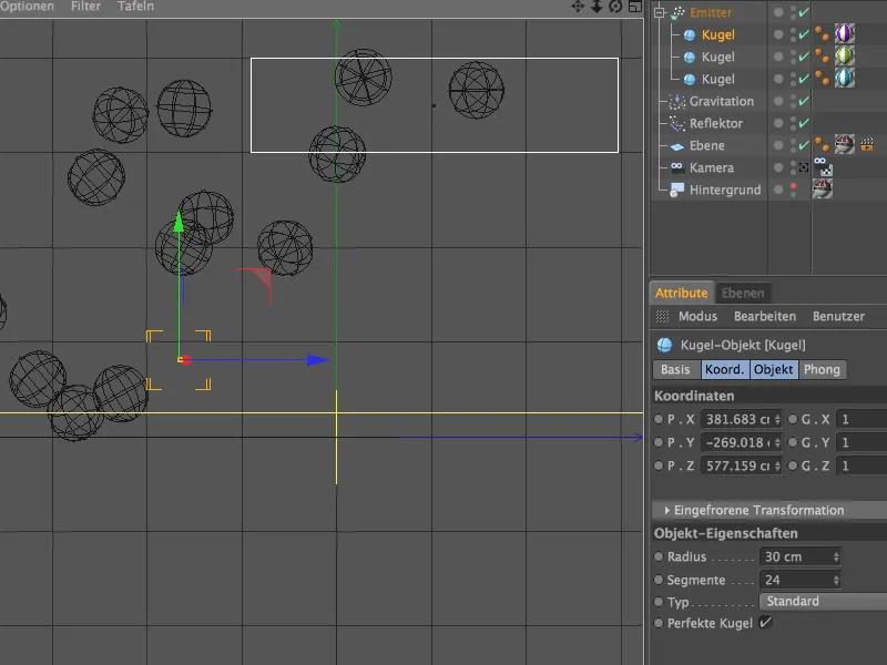
Illuminating the scene
Now that the camera has been calibrated and the 3D objects in the form of the particle system have been integrated into the scene, we still need to take care of adequate lighting.
We create a light object for the main shadow-casting light of the scene , which we give a slightly bluish tint on the general page of the settings dialog. This should bring the blue shimmer created by the sky and visible on the building and ground to the spheres.
We also activate a soft shadow or, if desired, an area shadow for the main light in the scene.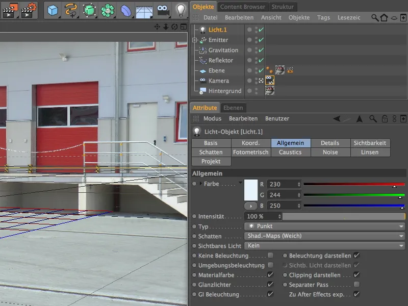
On the shadow page of the settings dialog, I have reduced the density of my soft shadow to 70% and selected a shadow map of 500x500. This makes the shadow look more natural as it mimics its brightening by indirect light.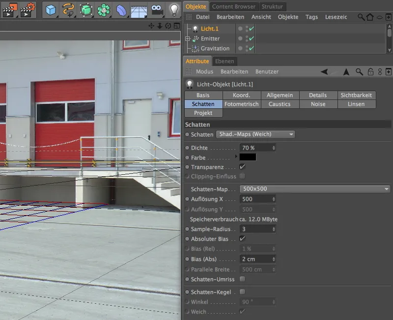
For the positioning of this main light, it is worth switching to the standard camera for a short time to make sure that the light source is well above the illuminated area. After all, the sunlight should be simulated reasonably accurately. Position the light source so that our main light falls as vertically as possible on the objects or the ground - this also corresponds to the incidence of light on our real image.
As the emitted spheres are only illuminated from above so far, we need additional light sources to simulate indirect lighting from the camera direction. To do this, we create two identical point light sources with a slightly yellowish tint and reduce their intensity to approx. 58% so that these light sources do not appear too dominant.
We position the first of these two so-called fill lights to the left of the camera. In the Y direction, it can remain at floor level, as we only want to simulate the indirect lighting from the side and from the floor.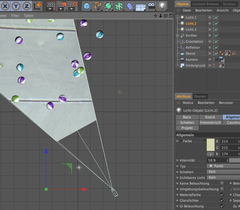
We position the second fill light opposite the first fill light on the other side. If you are not sure whether enough of the lighting will reach the spheres, simply let the animation run briefly and switch on the Gouraud shading in the orthogonal views.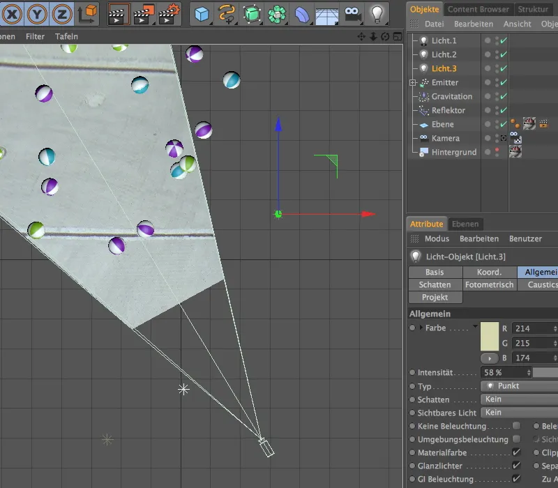
With extended OpenGL activated in the editor view, including shadow preview, the scene can now be assessed very well. Not only do the shadows look harmonious, the simulated indirect lighting also ensures that the undersides of the sphere are not in the dark.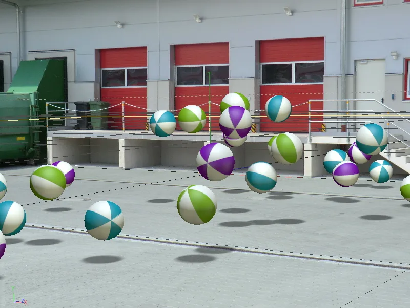
Here is a comparison of the rendered result of our now completed tutorial. Our 3D objects look harmoniously integrated into the scene, which actually only consists of a simple photo.