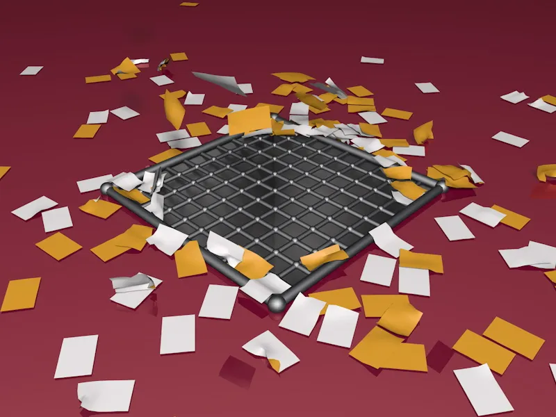
If you would like to follow this tutorial step by step, you will find the document "PSD_C4D_R14_Aerodynamik_start.c4d" in the package with the working files, which contains our common starting point.
The sheet of paper is a simple parametric plane object that has sufficient segmentation for deformation using dynamics. The paper is textured in two colors so that the lateral position is clearly visible and the scene is a little more colorful.
The grid cover consists of two atom arrays based on two plane objects. We are also working with two different objects here in order to be able to calculate collisions more accurately. The floor is not designed as a floor object, but as a polygon object, so that a hole could be created in the floor for the shaft, which is also a polygon object.
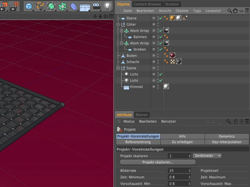
Equipment with dynamic properties
Let's start with the grid cover of the ventilation shaft. As already mentioned, we control the collisions of the paper with the grid here with two different objects and also dynamic body tags. To do this, we select the two atom arrays in the Object Manager and assign them a Dynamics Body Tag as a collision object using the context menu with the right mouse button or via the Tags>Simulation Tags menu in the Object Manager.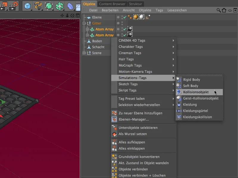
We select both Dynamics Body Tags in the Object Manager so that we can define the settings for both tags in one step. On the Dynamics page of the settings dialog, we keep the default settings.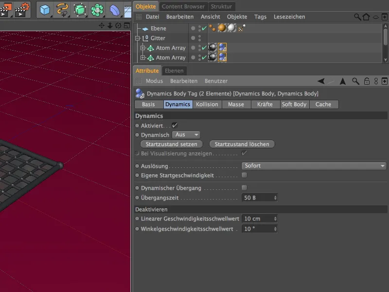
On the Collision page of the settings dialog, we can leave the form of collision as Automatic, since we are using two separate objects for the grid. We increase the friction value to 80% to make the sheets of paper that hit the grid slide away only slightly.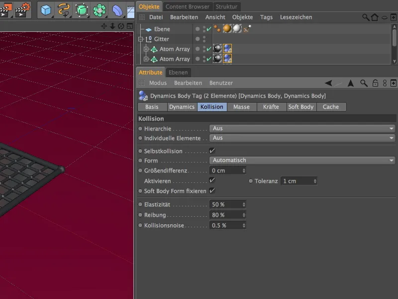
We continue with the floor. The polygon object of the floor is also assigned a Dynamics Body Tag as a collision object via the context menu using the right mouse button or via the menu Tags>Simulation Tags in the Object Manager.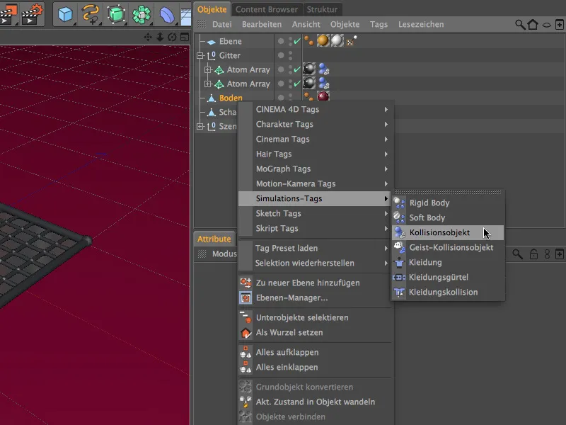
We can also use the default settings on the Dynamics page for the Dynamics body tag of the floor without making any adjustments.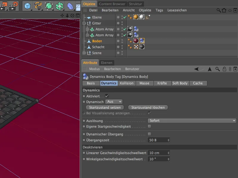
On the collision page of the settings dialog, we only need to adjust the friction to our requirements. To prevent the sheets of paper falling on the floor from sliding too far away, we increase the friction value to 150%.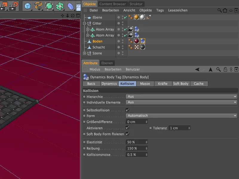
Finally, we come to the sheet of paper, which we will later let trickle down from above using a particle system. First, we take care of its dynamic properties. We therefore assign it a Dynamics Body Tag as a soft body via the context menu using the right mouse button or via the menu Tags>Simulation Tags of the Object Manager.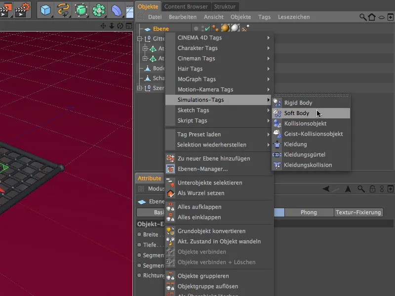
By selecting the soft body tag, the most important parameters are already set on the Dynamics page of the settings dialog. We also set the linear speed threshold a little higher so that the sheets of paper lying on the floor come to rest after a reasonable amount of time.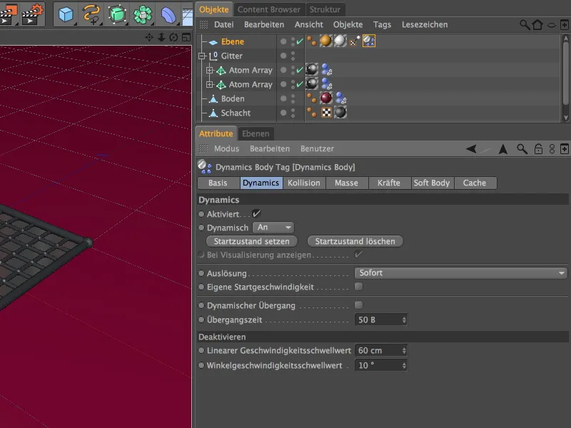
On the collision page of the settings dialog, we select the moving mesh as the shape. This ensures an exact calculation of the collision.
We reduce the elasticity to 5%; after all, the sheet should not bounce upwards after hitting the floor or grid. A friction of 50% fits well with the friction values already applied to the grid or floor.
On the mass page of the settings dialog, we use the density to determine the mass of the sheet of paper, which later falls to the ground by tens of particles. To tell the simulation that this is a very light flying object, we switch to Own density and assign a small value of 2.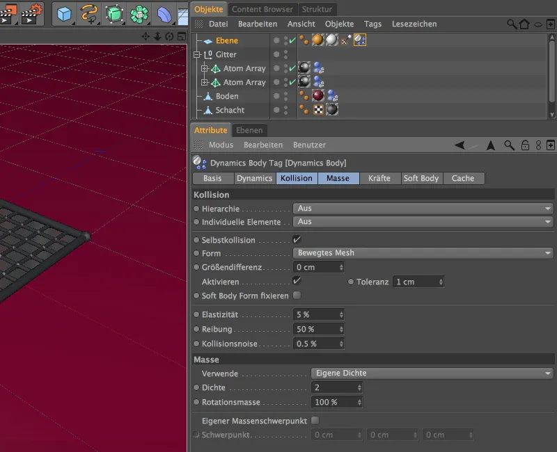
On the forces page of the settings dialog, we finally come to some crucial parameters for this tutorial - the aerodynamics. Since our paper blades have little to oppose when flying and under the influence of wind, we set the value for air resistance to a low 5%.
Conversely, we want the sheets to be able to straighten and lift even in light winds; a supporting value of approx. 70% is appropriate for lifting. The double-sided option ensures that not only the top side of the paper, but also the bottom side is recognized and treated as an attack surface.
So that our paper sheet can also behave like paper, we have created it as a soft body object, i.e. as an elastic, flexible body. On the soft body page of the settings dialog, we define the more detailed properties.
In order not to increase the calculation time more than necessary, we first deactivate the accurate solver in the soft body area. If miscalculations occur, we can still make improvements here.
We continue with the properties of the paper. Structure springs ensure the stiffness of the material, which is why we assign a relatively high value of 300 here, with 50% damping. The possibility of deformation after overloading, the elastic limit, which was added in version 14, is set late at 800%.
This ensures that not every piece of paper that hits the floor immediately remains wrinkled. To prevent the paper from simply collapsing, we increase the value for the shear springs to 100.
Naturally, paper does not have much to resist bending, which is why this value is relatively low. We also use the elastic limit here, but slightly lower so that creasing is permitted.
We use shape retention to determine how hard the deformed soft body object tries to return to its original state. A very low value for hardness is sufficient, as not much resistance is to be expected from the paper.
We set the elastic limit higher again so that the paper can simply remain deformed once it has exceeded this limit.
Structure of the particle system for the falling sheets of paper
After this parameter marathon, all relevant objects have been assigned dynamic properties. We now take care of the particle system that produces the sheets of paper and lets them trickle to the ground.
To do this, we bring an emitter from the Simulate>Particle system menu into the scene.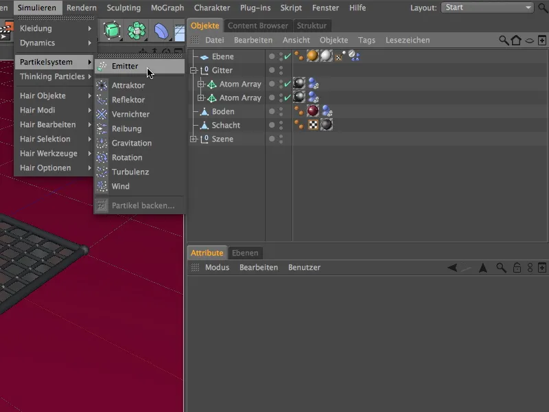
So that the sheet of paper can act as a particle, we create it as a sub-object in the emitter. Using the Y-coordinate value, we move the particle emitter upwards by approx. 300 cm; the position directly above the ventilation shaft is already OK.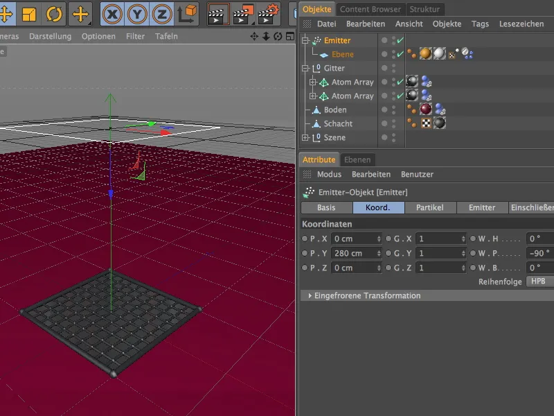
In the settings dialog of the emitter object, we control the emission of the particles via the particle page. Don't use too high birth rates here, because as these are soft body objects, the calculation is really computationally intensive. But don't worry, even with supposedly low birth rates (like my 10) you can accumulate a lot of paper.
So that the animation can end at frame 500 and every sheet is on the ground by then, we let the particle production end at frame 400.
By varying the speed and an additional rotation of up to 180°, the particle output looks natural. The Display objects option guarantees that we really see sheets of paper falling in the editor and when rendering.
On the emitter page of the settings dialog, we adjust the size of the emitter. The specified size is sufficient to fill the scene and the ventilation shaft with enough paper.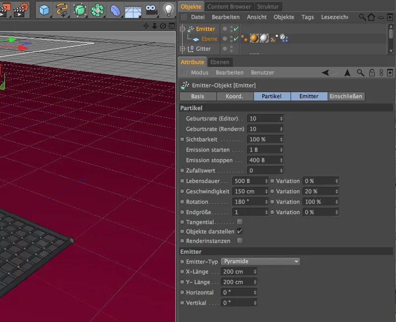
We finally test this by clicking on the play button and zooming in on the ventilation shaft in the editor. The sheets of paper fall down from above and collide with the grille cover and the floor as desired.
Installation of the air flow from the ventilation shaft
We haven't seen much of an aerodynamic effect so far, but this will change in a moment when we add an airflow coming out of the ventilation shaft to the simulation. To do this, we get the particle modifier Wind from the Simulate>Particle system menu into our scene.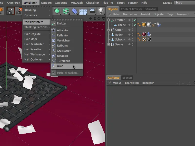
As the airflow is to emerge from the ventilation shaft, the position on the origin is already correct. However, we still need to rotate the wind by 90° using the pitching angle W.P so that the airflow points upwards in the Y direction.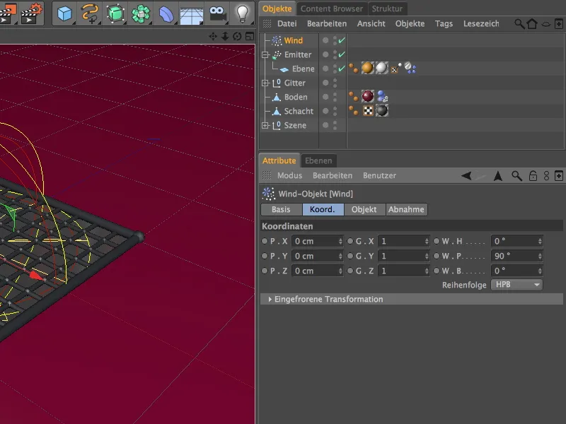
In the settings dialog of the wind object, we find the parameters for wind speed and turbulence on the object page. We will soon let the wind speed be controlled by chance, which is why we set 50 m here for initial tests. Turbulence is certainly desirable (after all, the wind flows through grids), but it is particularly important that we activate the aerodynamic wind mode, which can affect the aerodynamic properties of our paper sheets.
On the take-off side, we select the sphere shape as the take-off shape. Although this shape does not completely fill the corners, this is also in our interest, as it comes closer to the real situation and offers a little space for the paper to spread out on the grid.
The round spherical shape also means that the upturned sheets do not "lie" on one edge of the modifier and float impassively. We set the decrease to 10% and select the option Inv. square for the decrease function.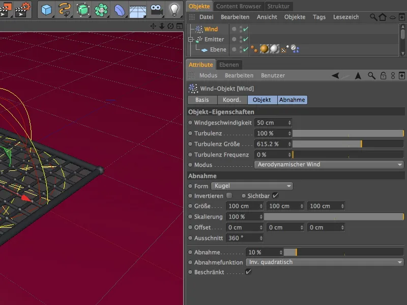
A click on the play button shows how the outflowing wind now influences the falling sheets of paper. However, the air flow is currently still too uniform.
Controlling the air flow via XPresso
With a small XPresso circuit, we can help the air shaft to generate sudden gusts of wind without having to animate any parameters.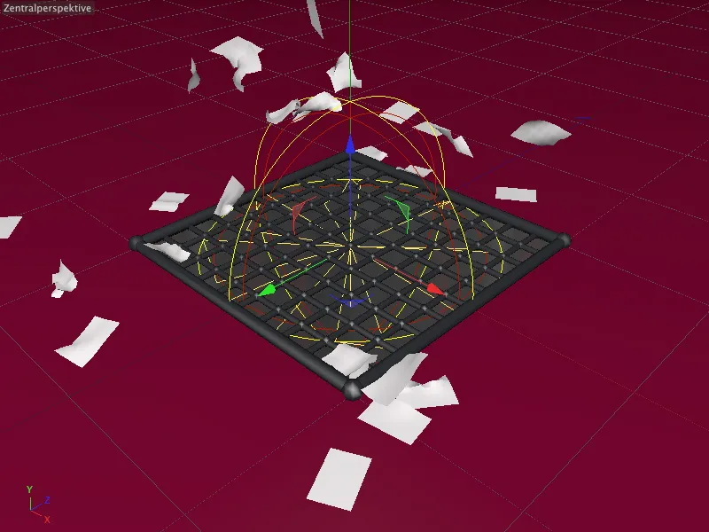
To do this, we need an XPresso expression, which we assign to the wind object as a carrier. We can find the expression either via the context menu using the right mouse button under the CINEMA 4D tags or in the menu Tags>CINEMA 4D Tags of the Object Manager.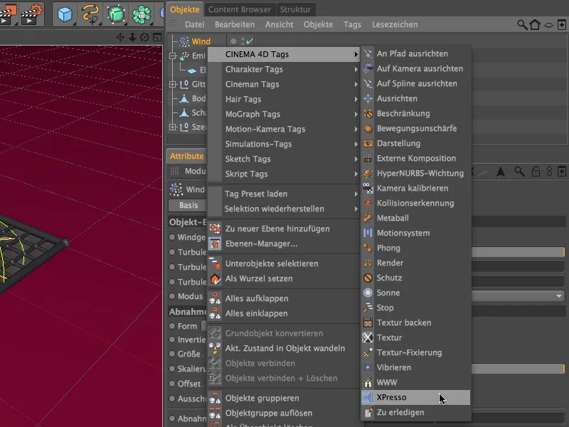
We open the XPresso editor by double-clicking on the XPresso expression icon in the Object Manager to create our small circuit. To be able to address the wind object, we need it in the XPresso editor. Therefore, we simply drag and drop it from the Object Manager into the XPresso Editor.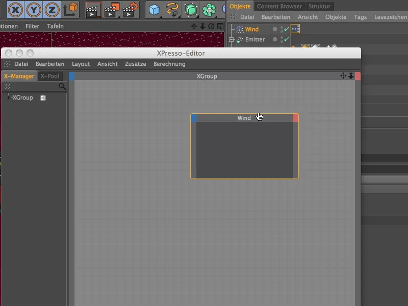
On the blue input port button of the wind node, we select the wind speed parameter in the object properties menu to make it available as an input port.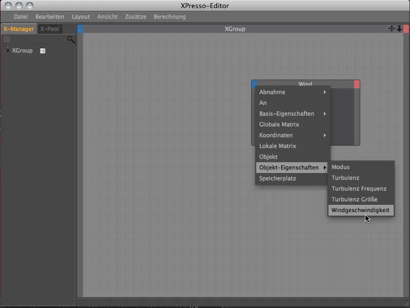
On the one hand, the generated wind speed should be within a predefined range of values, but on the other hand, it should not have any unusable value jumps, but should always rise and fall. The noise node is ideally suited to these requirements, which we can bring into the XPresso editor using the context menu with the right mouse button.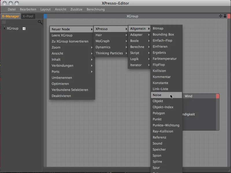
The noise port is already available as an output port on the noise node. By dragging with the mouse, we connect the noise port with the wind speed input port of the wind object node.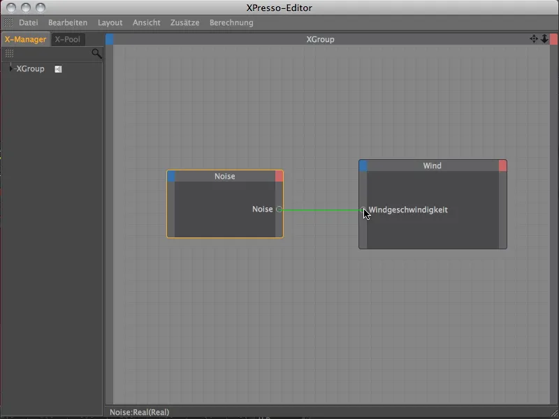
The wind speed parameter is now controlled by a noise texture. This texture and its processing can be regulated via the settings dialog of the noise node.
We select the wave-shaped turbulence and also allow negative values by deactivating the Absolute values option. We use the Size parameter to scale the noise in order to create smooth transitions. We use the frequency to control the frequency of the noise changes over time.
A relatively low value of 0.5 ensures that the gusts of wind do not occur too quickly one after the other. The amplitude multiplies the noise result by the noise value that is passed. Here, we use 150 units to ensure significant swings. The start value 0 allows our wind machine to begin with no wind.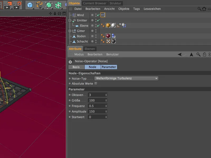
In the settings dialog of the wind object, the control of the wind speed via XPresso is noticeable through a changed parameter box. If we click on the play button, we can see very clearly how the wind speed value changes over time - and we can also recognize the noise-based rotor rotation of the wind modifier in the editor.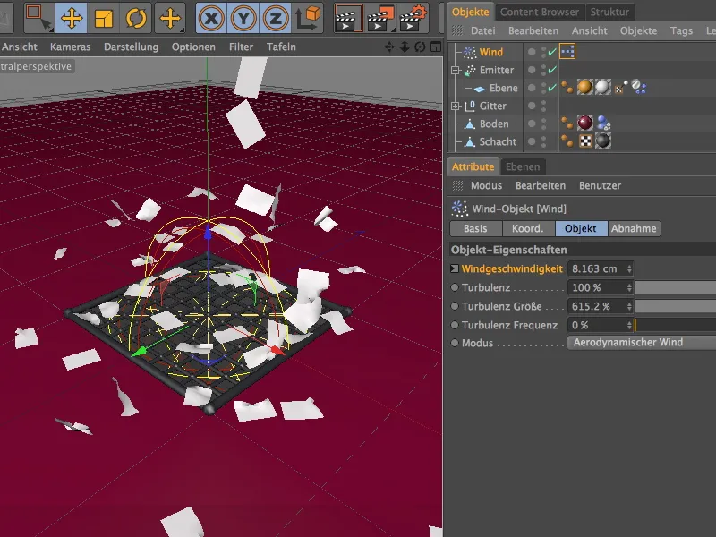
Image-controlled activation of the wind object
In order to give the paper leaves the opportunity to settle and collect on the grid, we only activate the wind object at frame 150. We do this using a small parameter animation.
To do this, we set the time sl ider to frame 0 or 1, switch off the wind object via the Activate parameter on the base page and click on the parameter circle while holding down the Ctrl or Ctrl key to save a keyframe for this value.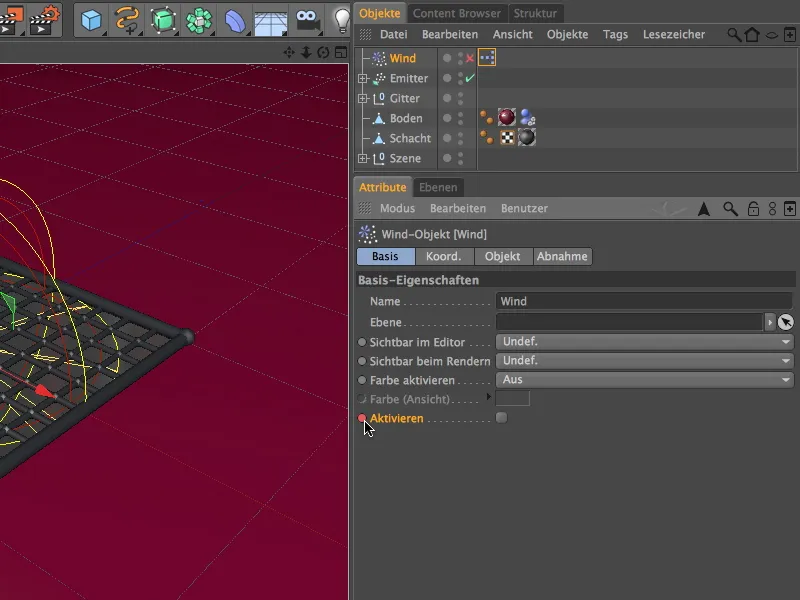
We then set the time slider to frame 150 and record a keyframe for the Activate parameter with the wind object switched on.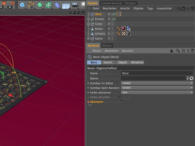
There is nothing more to do with this small parameter animation. The rotor blades of the wind object now stand still until frame 149 and only start moving from frame 150.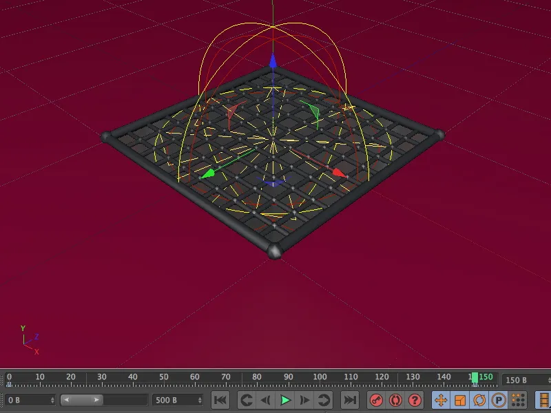
Checking the Dynamics presets
If you have used my original scene for reworking this tutorial, there should be no need to make any changes here. In the project presets in the Edit menu on the Dynamics page, we can find some parameters that help the Dynamics solver to avoid errors during processing.
In the General section of the Dynamics preferences, we only need to ensure that gravity and density are global. The air density parameter is important for the aerodynamic simulation.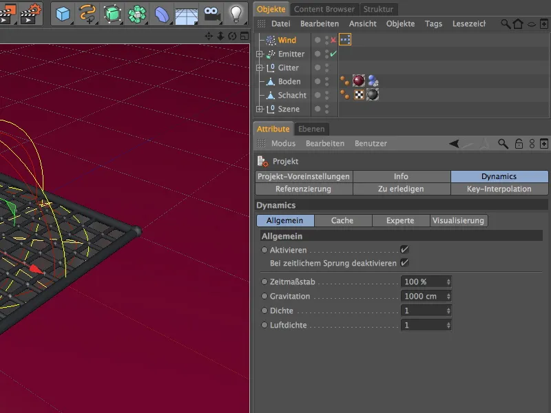
In the Expert section, we can help the Dynamics solver by lowering the scaling. We are mainly dealing with 20 cm x 30 cm sheets of paper that are to be deformed and collide fairly precisely. A value of 5 cm creates a better understanding of the size for the Dynamics engine.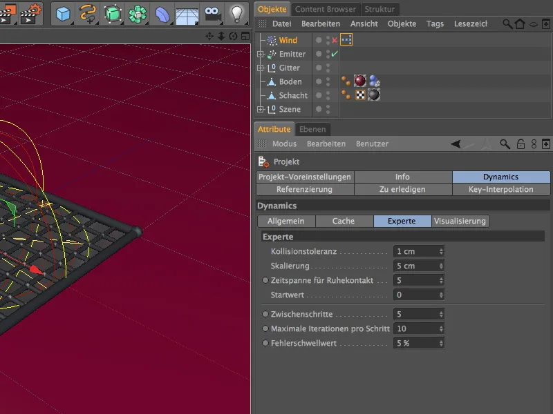
Now we can run and render the finished simulation in its entirety. In several gusts of wind, the sheets of paper collected on the grid are repeatedly whirled upwards thanks to aerodynamics...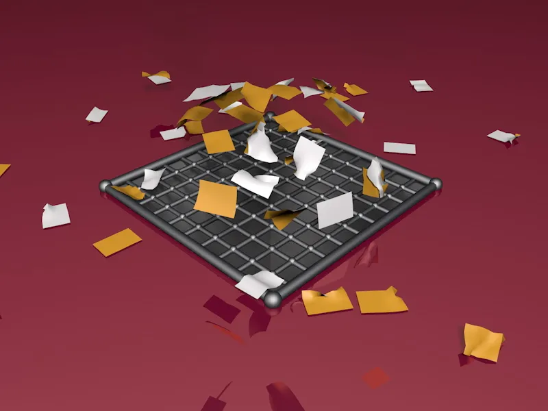
... and can finally only stay on the wind-protected areas of the grid.