In order to follow the innovations in CINEMA 4D 13 shown in this tutorial exactly, you can either use the example files provided or quickly build your own scenes with basic objects that are as simple as possible.
Outside indicator
If you often get lost in the multitude of scene elements when working in the editor, you will be pleased to see the new outside indicator. As soon as a selected object is no longer visible in the editor view, a blue arrow shows you where to navigate to this object.
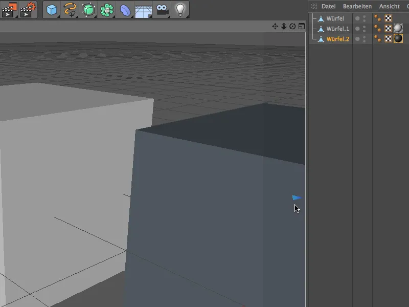
You can navigate to the selected object particularly elegantly by simply clicking on the blue outside indicator. The object you are looking for is now in the center of the editor view.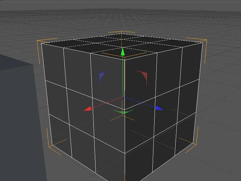
Improved camera navigation
Very soon after starting CINEMA 4D 13 for the first time, most users will notice that navigation in the editor now "feels" a little different. This is partly due to the automatic increase or decrease in camera speed, but also to the improved camera navigation options with a point of interest PDI and various camera modes.
You can find the four different modes in the Cameras>Navigation menu in the Editor view. What's really new in CINEMA 4D is the default cursor mode.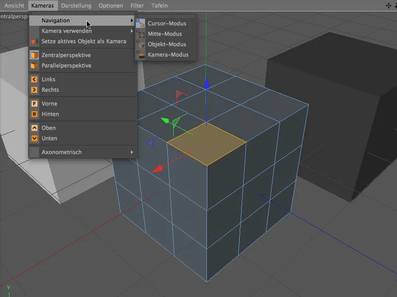
Let's take a look at this new cursor mode first. Activating the three view tools Move, Scale and Rotate with the 1, 2 and 3 keys should already be second nature to most CINEMA 4D users. Simply click on the desired reference point for navigation with the mouse pointer while holding down the view tool button and move, zoom or rotate the view. This self-selected reference point is displayed as a yellow cross during navigation and is considered the point of interest (PDI) during this time.
After a short period of familiarization, you will no longer want to do without this very practical and fast way of navigating.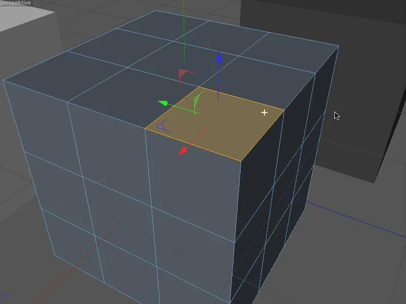
The center camera mode causes the center of the view to be used as the reference point for navigation.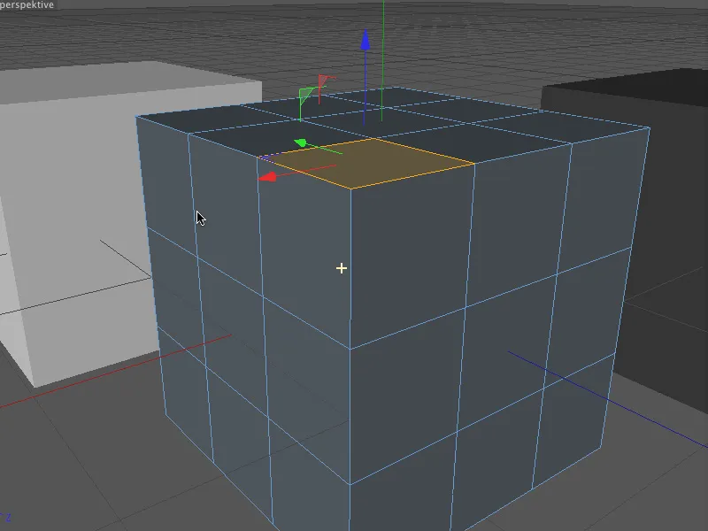
Object mode was the standard mode in Cinema 4D for a long time. Here, the center of the selected object or element provides the reference point for camera navigation.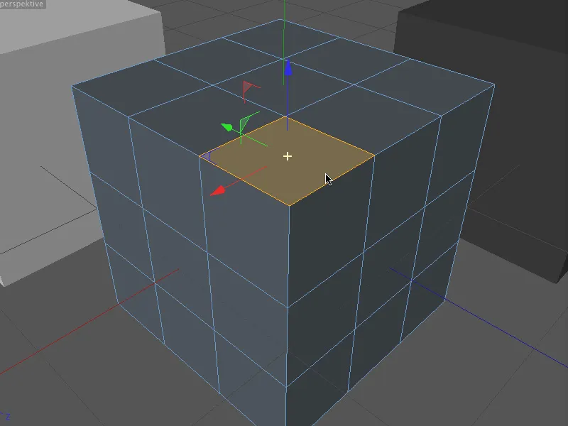
Camera mode is less suitable for working on objects and more for navigating the scene. In this mode, the camera rotates itself but does not move.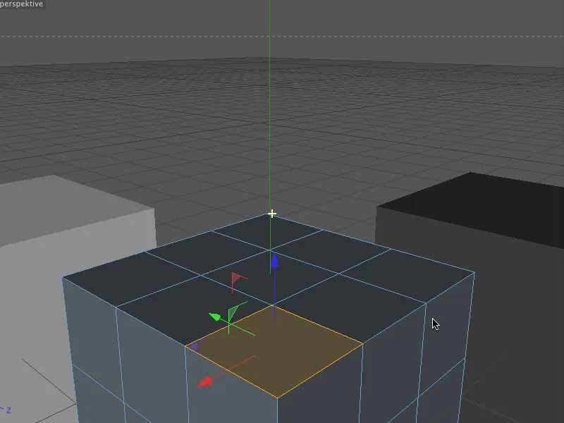
Object and group editing
Before version 13, the task of modifying several objects individually by a certain value was quite cumbersome. Thanks to the improved tool and axis functionality, a single mouse click is now all it takes.
In the example shown, the three cubes are to be rotated once together and once individually for comparison. If all the elements concerned are selected and the rotation tool is activated, the common modification axis with the rotation bands is displayed in the editor.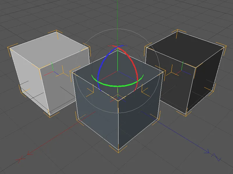
When rotating along one of the three rotation axes, all three cubes follow this common manipulation. We are familiar with this behavior from previous versions of CINEMA 4D.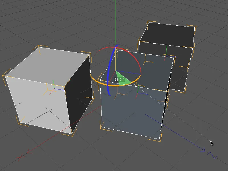
New in version 13 is the option Manipulation per object, which we find on the object axis page of the Move, Scale and Rotate tool.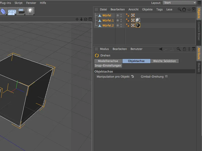
If we have activated this option, the manipulation is done separately for each object so that we can apply the desired rotation to each selected object individually.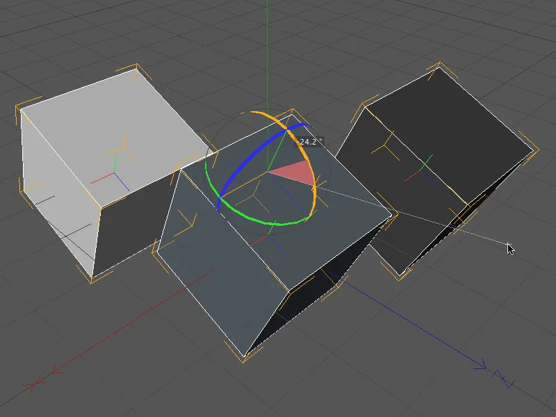
Snapping with extended axes
Another very practical new function is snapping using extended axes. With this method, objects can be quickly and easily placed on or aligned with other objects and their elements.
In this tutorial, I will show the workflow in great detail so that the few steps required are easy to memorize.
First of all, we need active 3D snapping for the desired elements. The new range of snapping functions integrated in version 13 is very helpful here and allows us to make all the necessary settings via the editor.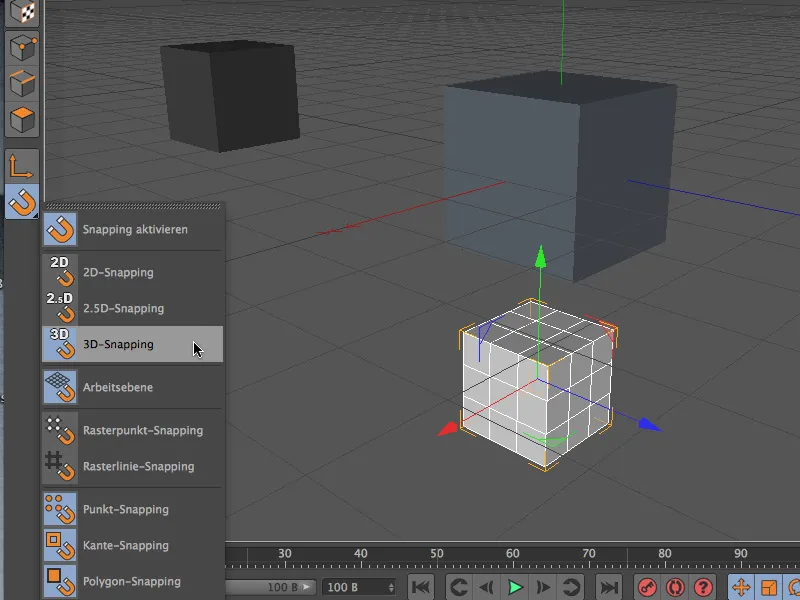
Alternatively, the snapping can of course also be changed as usual via the settings dialog of the respective tool. There you will find all the required parameters on the Snap settings page.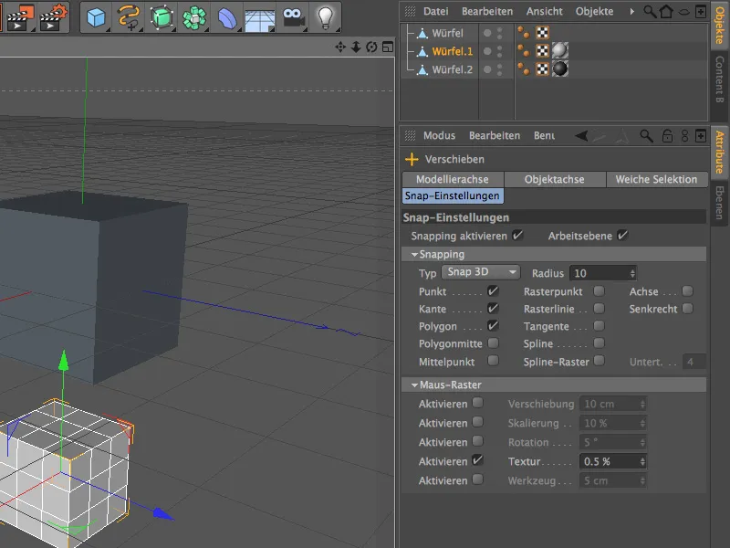
In our first small example, two small cubes are to be placed flush with the top and bottom corners of a larger cube using only the new snapping functionality of the extended axes.
To do this, we first select a suitable perspective in the editor view and decide on the first axis along which we want to move the small cube. To prepare the axis for snapping, we hold down the Ctrl key and right-click on the selected axis.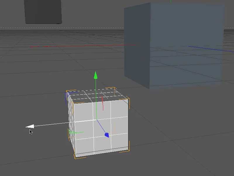
The axis of the cube can now be shortened or lengthened as required by moving the mouse pointer in both directions. We select the outermost point on the side face of the cube as the axis length and, holding down the left mouse button, aim from there at the desired target element with which the axis pointer should be flush. In our case, the front right edge of the large cube is best.
During this process, the cube was immediately moved to the respective position by snapping.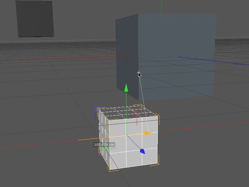
Let's continue with the Z-axis of the light cube. Here, too, we prepare the axis for snapping by holding down the Ctrl key and clicking on the selected axis with the right mouse button.
We shorten the axis of the cube by moving the mouse pointer to the outermost point on the side surface of the cube and from there, with the left mouse button held down, aim at the desired target element with which the axis pointer should be flush. In our case, this is again the front right edge of the large cube.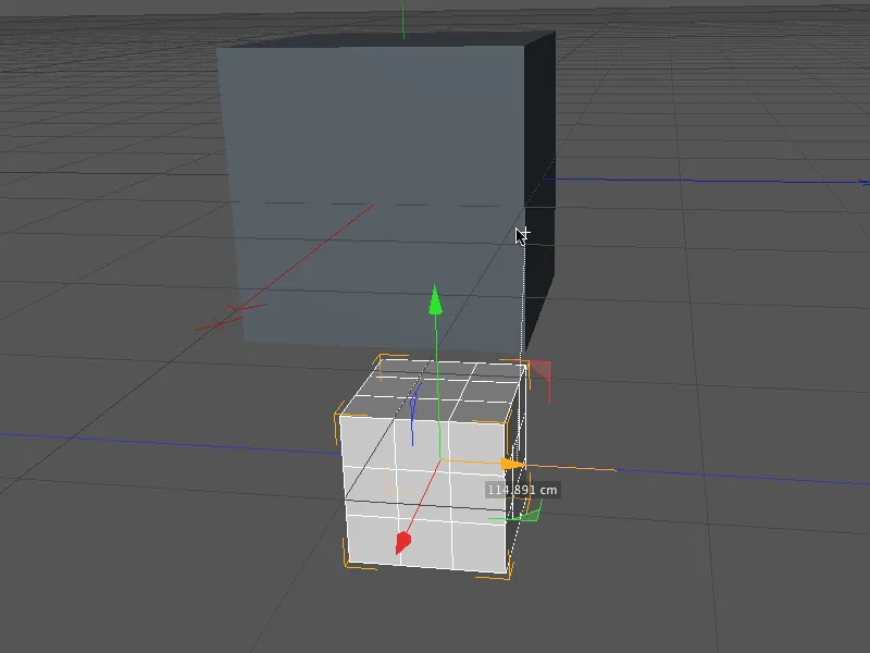
Finally, we now make the Y-axis editable in the same way ...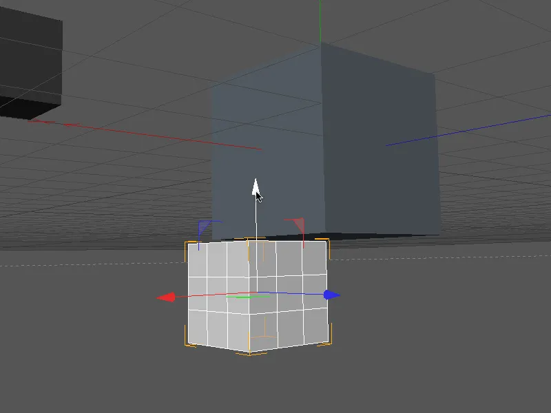
... set the reference point for the axis to the bottom of the cube ...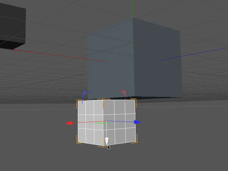
... and move the small cube flush by using a point on the underside of the large cube as the target element.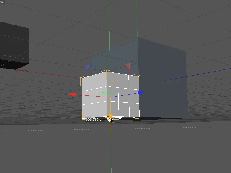
This would position the light cube correctly on the large cube - using only snapping with extended axes.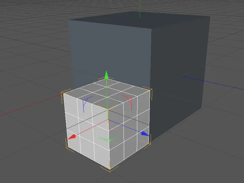
Because practice makes perfect, we attach a second, dark cube flush to the top left corner of the cube in the same way. Again, we prepare the axis for snapping by holding down the Ctrl key and clicking on the selected axis with the right mouse button.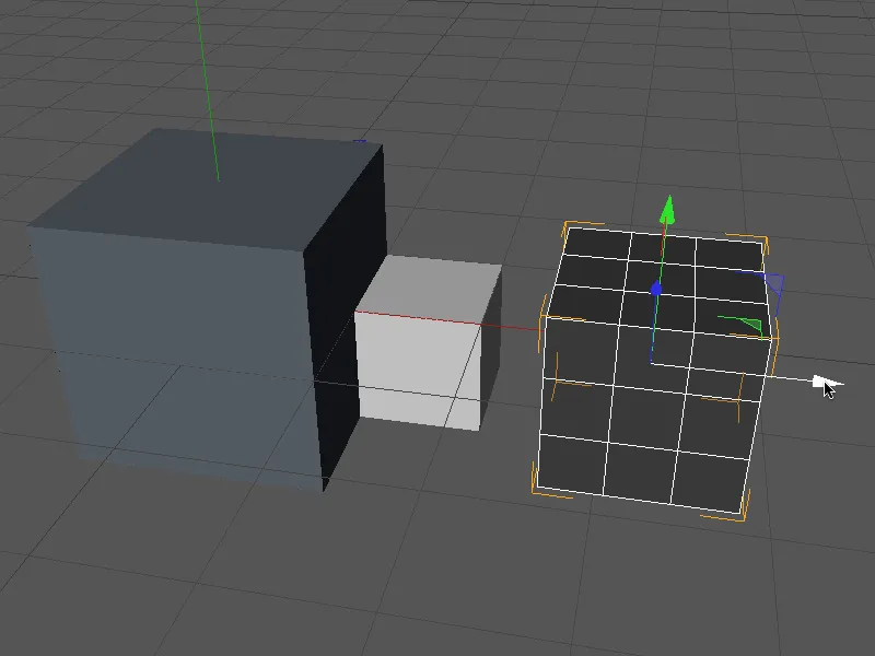
We extend the axis of the cube by moving the mouse pointer to the outermost point on the side surface of the cube and from there, with the left mouse button held down, aim at the desired target element with which the axis pointer should be flush. In our case, this time the front left edge of the large cube.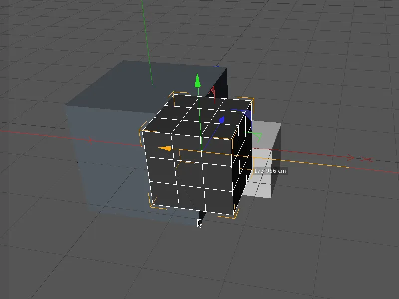
We switch to a clear perspective and take care of the Z-axis of the cube. Again, we first make the axis editable ...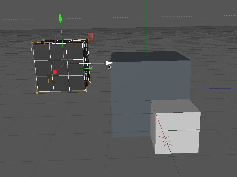
... set the reference point for the axis to the outer side face of the cube and position the cube flush with the target element of the left front edge.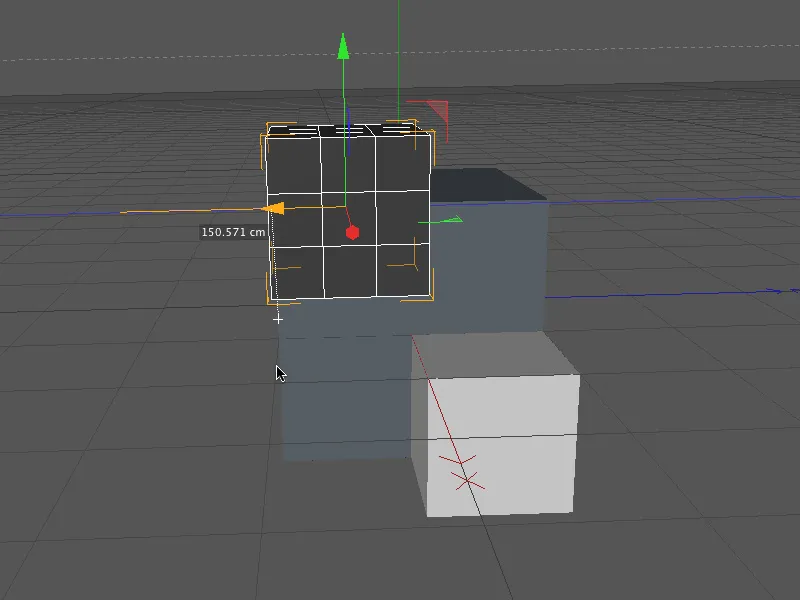
In the last step, we now have to position the dark cube flush with the upper edge of the large cube in the same way by snapping with the extended Y axis.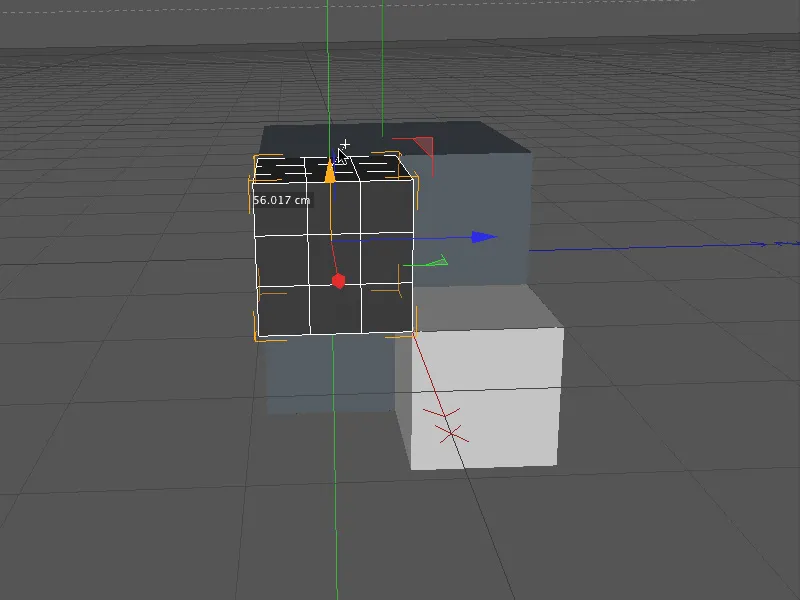
Now all three cubes are positioned exactly in relation to each other and the handles for this practical innovation should really be in place.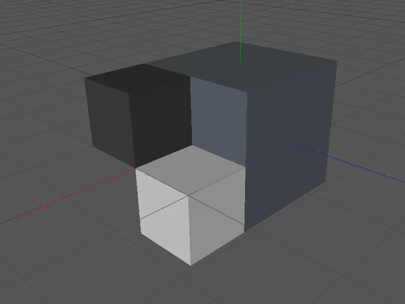
We can now turn our attention to another example of snapping with an extended axis, this time in conjunction with the rotate tool. In the example shown, a cuboid bar is to be rotated exclusively by snapping so that it lies diagonally exactly on the line between the two corner points of the large cube.
We activate the rotation tool and use the snapping palette to ensure that 3D snapping is also still active.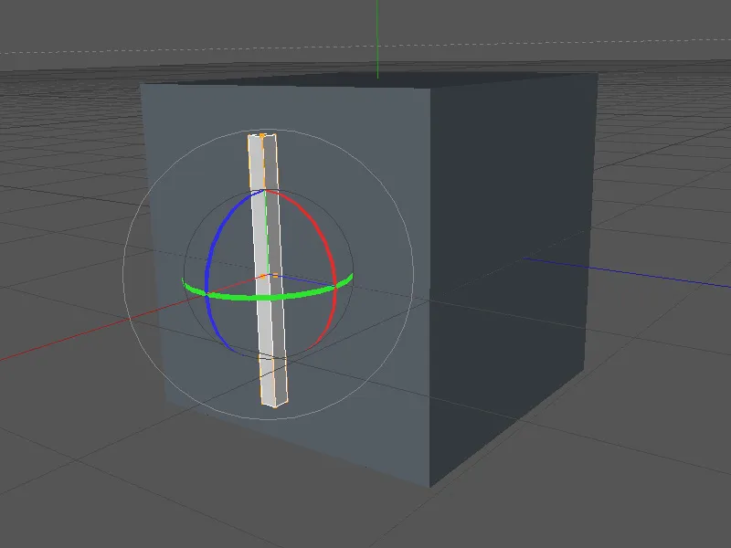
To prepare the rotation axis of the rod for snapping, we hold down the Ctrl key and right-click on the rotation band . The rotation axis of the rod selected via the rotation band can now be rotated as desired.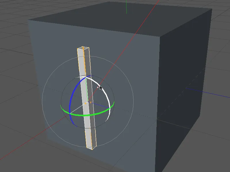
Similar to working with the move tool, we again select a reference point for the rotation, in our case the center of the bar at the top end, and from there, with the left mouse button held down, aim at the desired target element in the direction of which the rotation should be exactly positioned. In our case, the upper right corner point of the large cube is best.
The bar rotates to the desired diagonal position while the target element is being selected.
The new navigation and tool functions presented in this tutorial can make working in CINEMA 4D much easier once you have discovered them.


