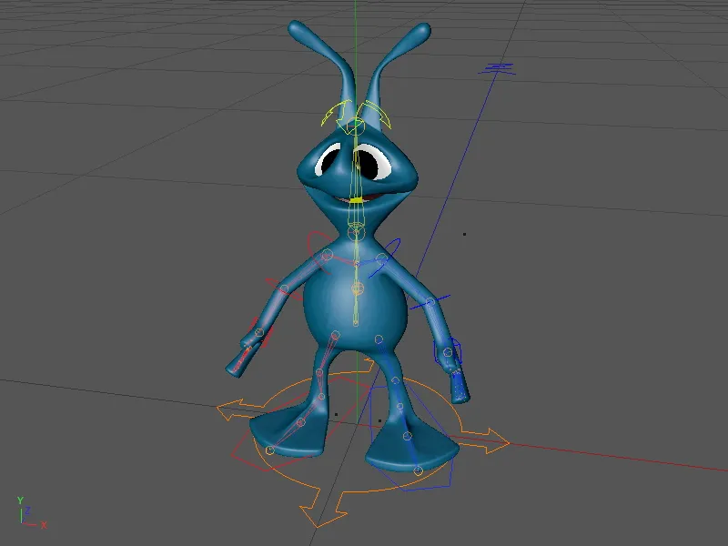
In this tutorial, we will equip an alien biped with a functional character rig. You can use the alien character in the corresponding working file "PSD_C4D_R13_Charactervorlagen_Start.c4d". Of course, you can also use any other character for this tutorial; the essential steps remain the same (at least for bipeds ).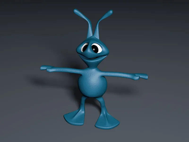
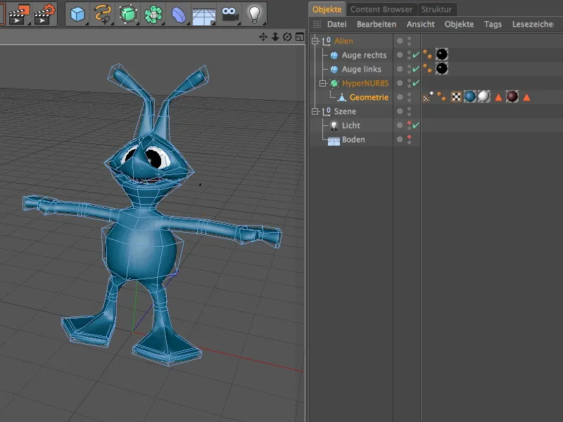
Let's take a quick look at the structure of the scene/character in the Object Manager. The character essentially consists of a polygon object smoothed using a HyperNURBS object ; the two eyes are simply placed parametric sphere objects. The textures of the alien are already fixed using a texture fixation tag, so we can start rigging straight away.
Building the rig
The character is built using the character templates included in CINEMA 4D Release 13 via the character object from the Character menu.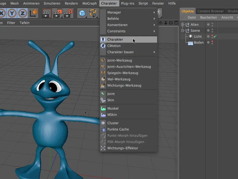
Before we start creating the components for our alien, we will give you a few key points to help you. On the basic page of the settings dialog for the character object, we can define that it is an alien from the Character menu, for example.
The size parameter gives the character object an indication of the size of the character (in my example, I have not included the antennae). The advantage of this is that when the components are created immediately afterwards, a fairly useful position for the elements is already estimated.
The next important basic specification is the type of character so that the correct character template is used when creating the rig. On the object page of the character object, we find the Biped template in the Build tab.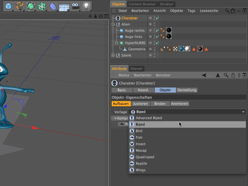
Now we can start building the rig. Thanks to the character template, we are only offered the components that make sense or are anatomically possible for the creation. We start with the hips by clicking on the Pelvis button.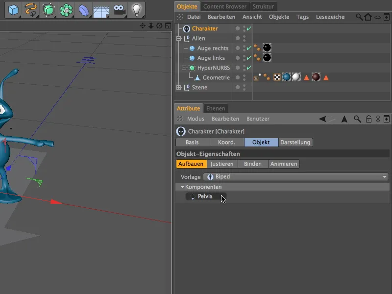
We continue with the spine and install the Spine (FK) componentvia the now available Spine menu.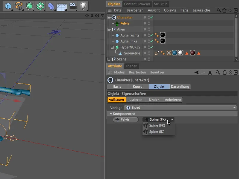
As the spine component is the starting point for the arms, head and legs, we are now also offered these components for creation. We use the Head button to add a head component to the character.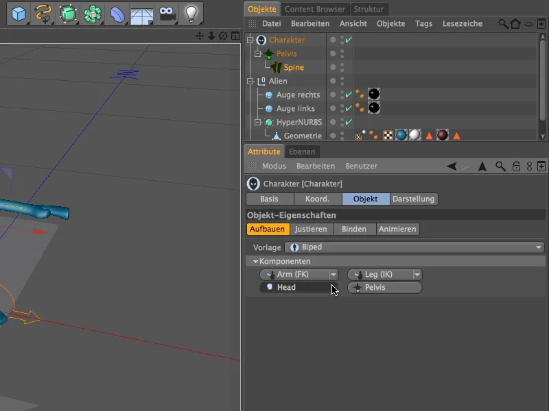
Now we have already created the first components for our alien character; however, these components are not yet positioned exactly despite the default settings.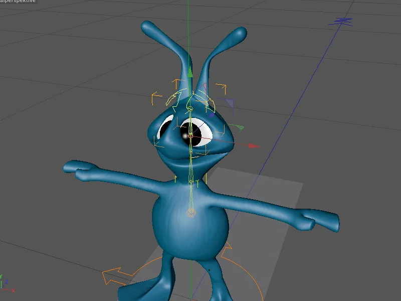
In order to adjust these components correctly to the character, we briefly switch to the Adjust mode. Just click on the tab of the same name on the object page of the character object.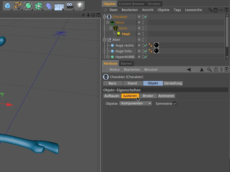
To make the adjustment of the components as clear as possible, the character object displays the components as small spheres. If you move the mouse pointer over one of the elements, you will even see its name.
Before we create the next components of the rig, we place the existing components in the correct positions. To do this, we switch to the front view (F4 key) and start with the lowest component of the spine. In my example, I have placed the pelvis component, which as a hip represents the top level in the hierarchy, slightly higher in the middle of the character (green sphere) to make it easier to reach - but this does not change anything functionally.
The individual components can simply be moved to the desired position using the move axes.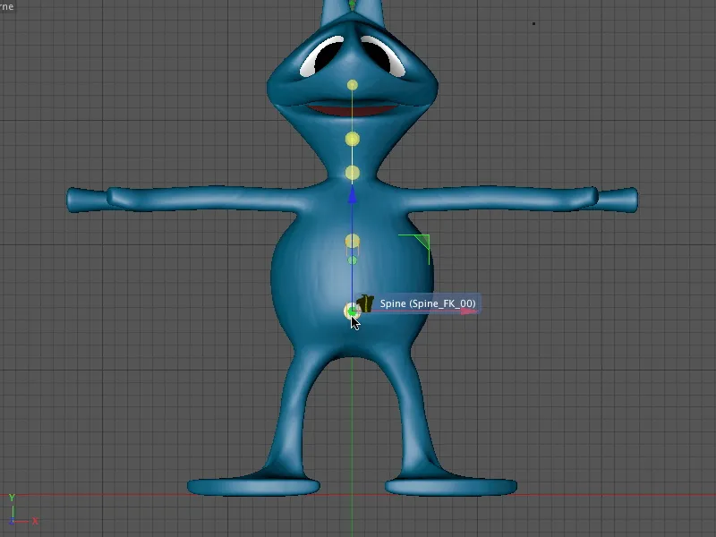
We can distribute the individual elements of the spine along its length until we reach the neck. This is the last part of our alien character's spine.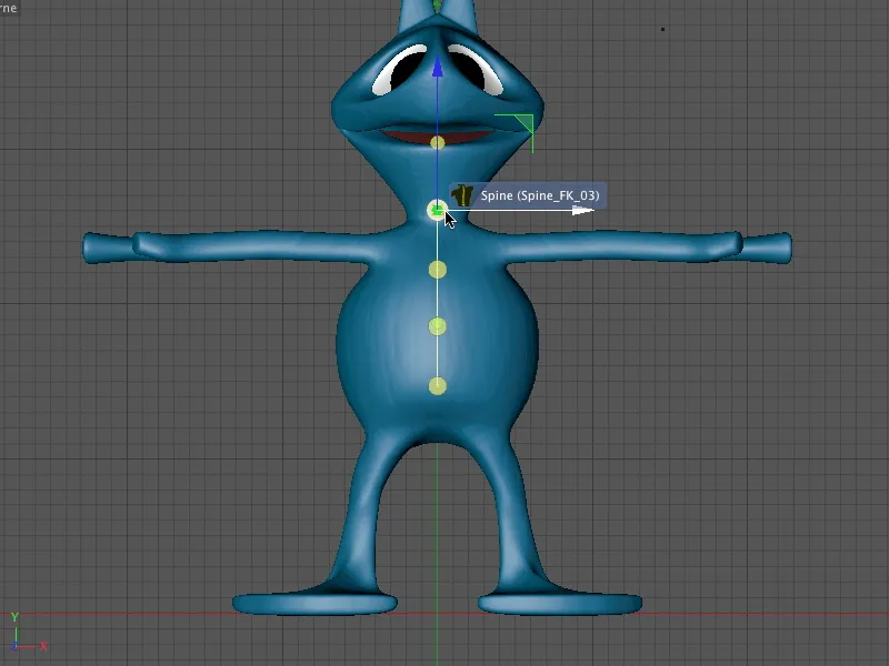
Finally, we move the head component to the top of the head. The control element for the head will also be accessible there later.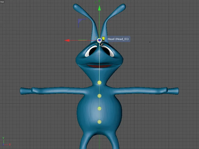
We switch to the side view from the right (F3 key) in order to be able to position the components correctly in the Z direction. To do this, we start again at the lowest point and work our way up component by component to the top of the header.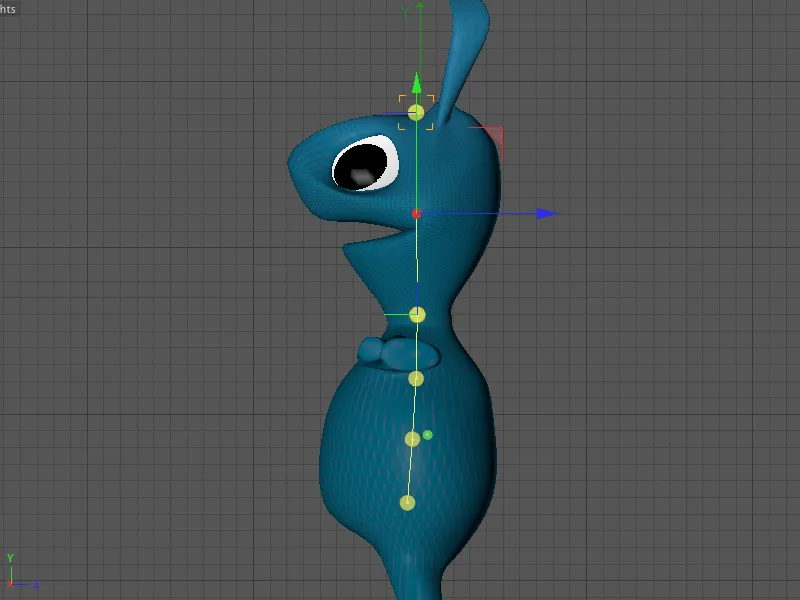
This means that all of the character's components are now in place. If we now exit Adjust mode by switching back to Build mode, we already have a first impression of the associated control elements for the character.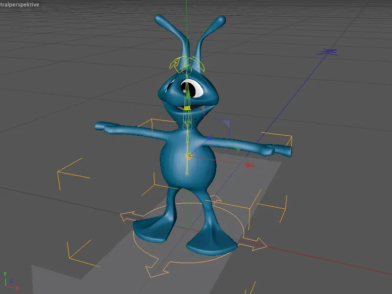
Back in Build mode or in the settings dialog of the character object, we continue with the legs. To do this, we select the Spine object in the component hierarchy and can access the Leg menu. To create the legs in pairs for left and right, simply hold down the Ctrl or Ctrl key when clicking on the Leg (IK) entry.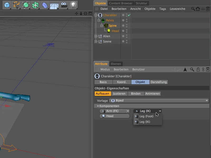
The same applies to creating the arms. Here too, hold down the Ctrl key and select the Arm (FK) or Arm (IK) entry, depending on how you want the arms to be animated later. In order to show you how FK (Forward Kinematics) and IK (Inverse Kinematics) work, I will select the FK variant for the arms at this point.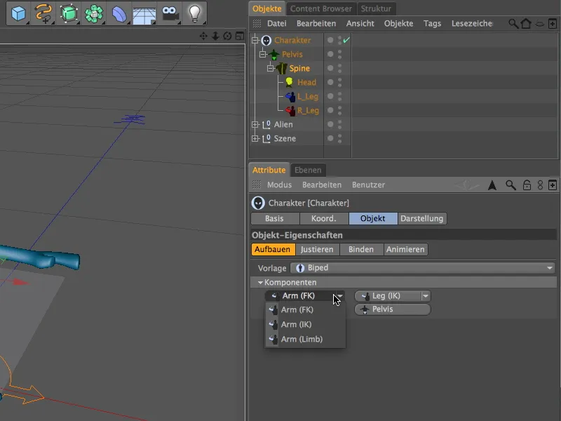
With the arms, we have now created all the necessary components for our alien character so that we can adapt the newly added components to the alien in Adjust mode.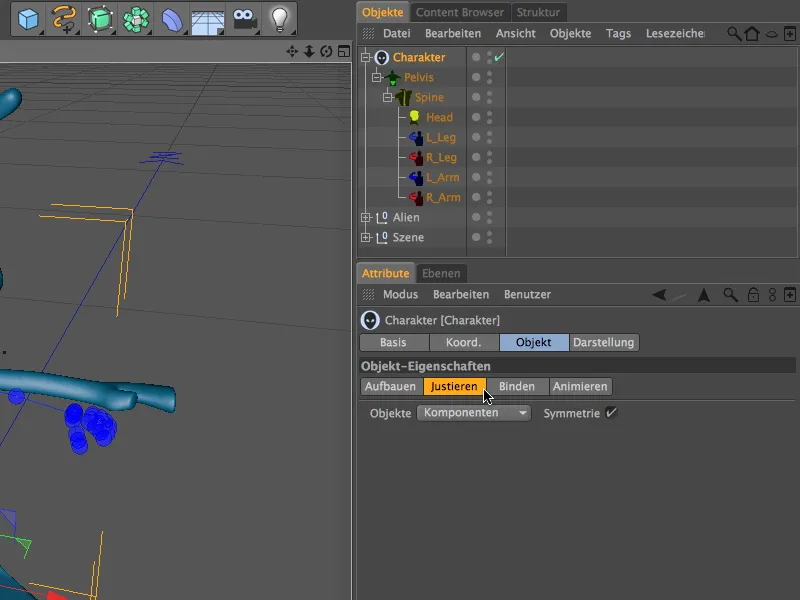
A look at the editor view shows that the new components do not fit exactly in the right places (that would be pure coincidence), but thanks to the predefined character size and the existing components such as the spine and head, the editing effort is limited.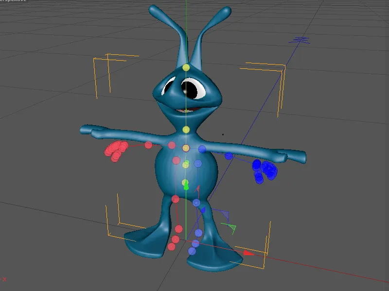
We switch back to the front view (F4 key) and start adjusting the leg components. Conveniently, the components work symmetrically (see Attribute Manager), so that it is sufficient to take care of one of the two sides; the other side is automatically adjusted in mirror image.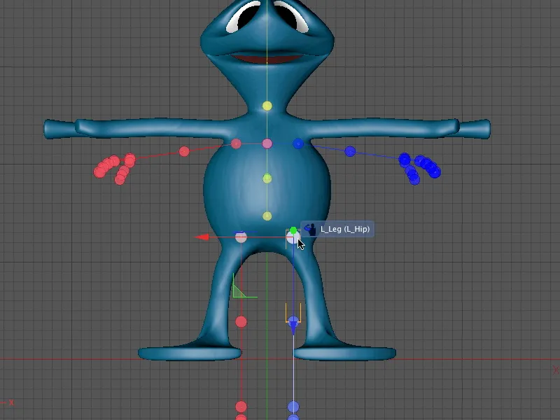
We place the components of the legs step by step from the front view, from the base of the leg to the knees to the ankle and the tip of the foot.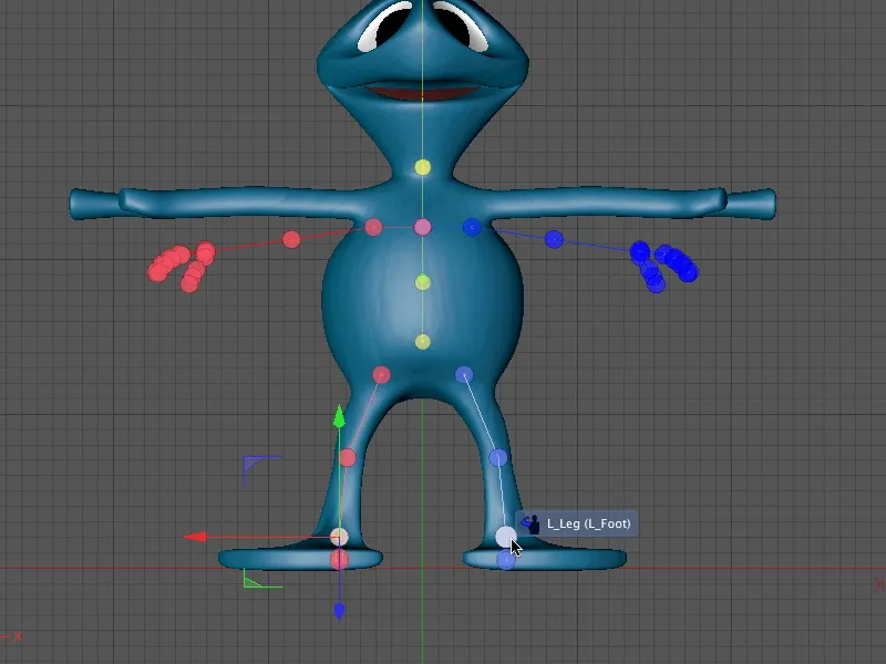
We then switch to the side view (F3 key) so that we can also adjust the leg components to the alien in the Z direction. Start again at the first position in the hierarchy, otherwise you will have to constantly readjust the attached components.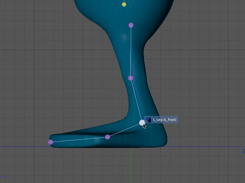
As the alien unfortunately does not have a humanoid standard foot, the central perspective (F1 key) is also required when adjusting the tip of the foot.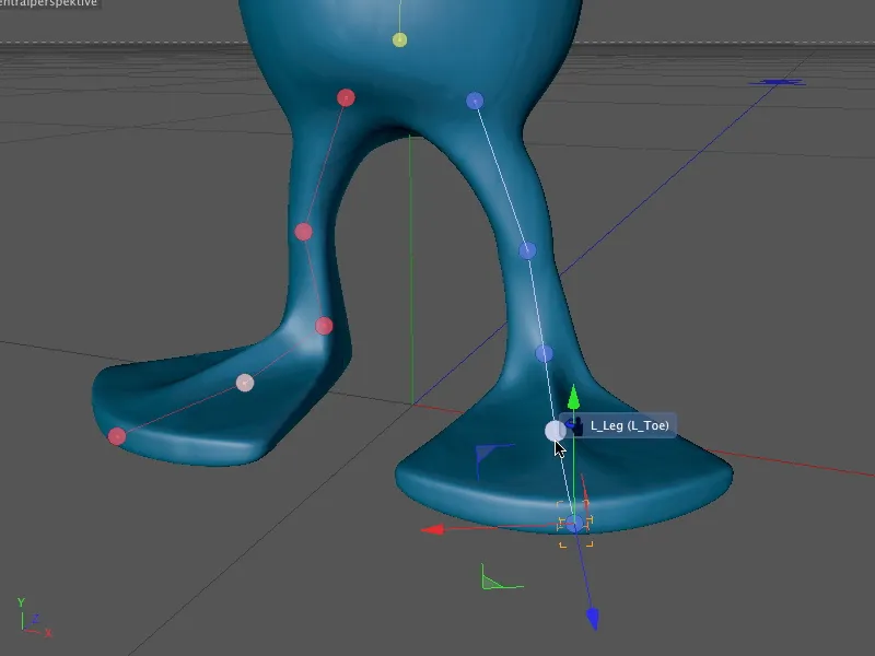
With the legs and feet done, we can now take care of the alien's arms. We start again at the top of the hierarchy, at the shoulders, and place the corresponding component from the front view (F4 key) in the appropriate position.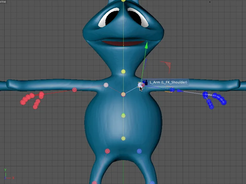
This is followed by the component of the elbow, which should be positioned fairly precisely in the bend of the alien's arm, which is equipped with more polygons, in order to allow the geometry to be angled without any problems.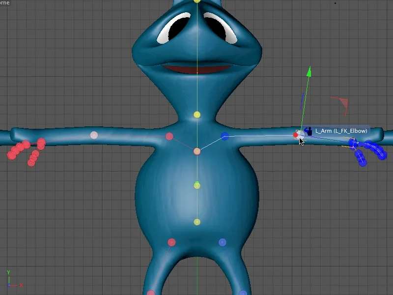
As you have probably already noticed, the modeled alien hand only has two larger fingers. Nevertheless, we use the human "five-finger system" - firstly, to be able to continue working with the character template. Secondly, thanks to the included animatability, it is possible to move the chunky fingers well.
If you have used a different character for this tutorial, you can of course adapt the individual components of the fingers to the existing geometry below.
To move the entire hand including the fingers, select the hand component and move it to the position of the wrist.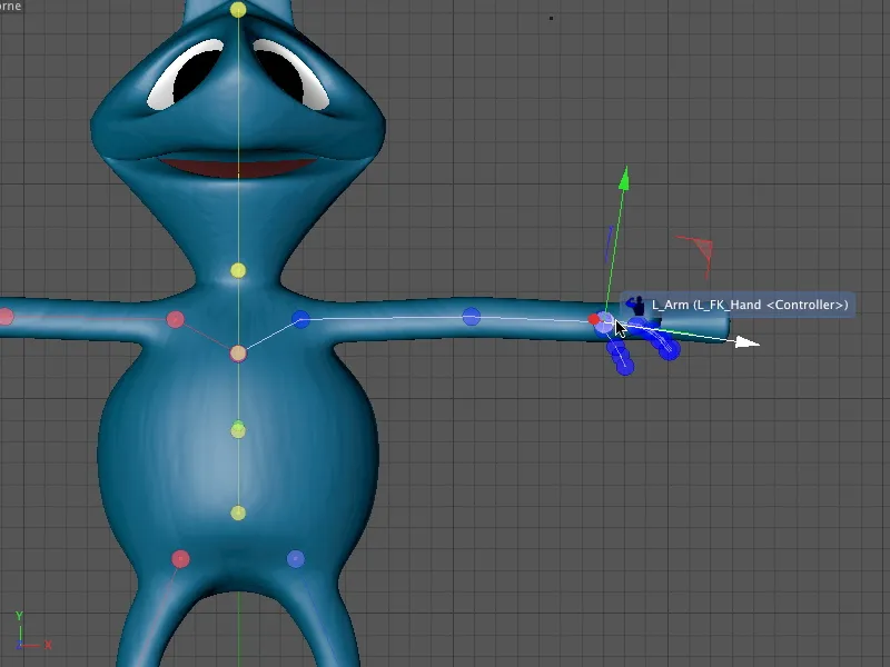
The next step is to adjust the arm components from the central perspective (F1 key). This gives you a good overview of the actual position of the component.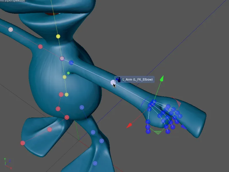
As already indicated, the three extra fingers are not superfluous. We simply place them well distributed over the geometry of the alien hand. As each of the fingers can be animated using the character template controls, we can control each area of the hand.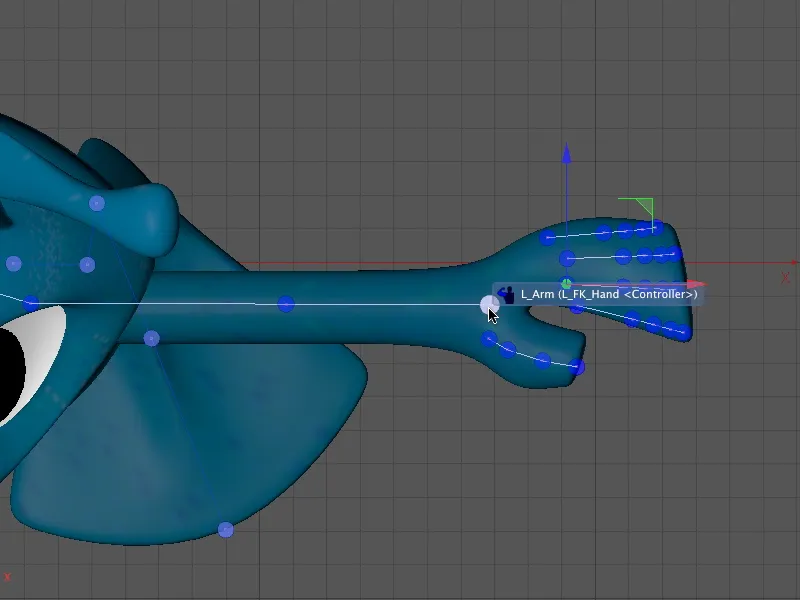
Last but not least, we check the position of the arm and hand components from the central perspective (F1 key).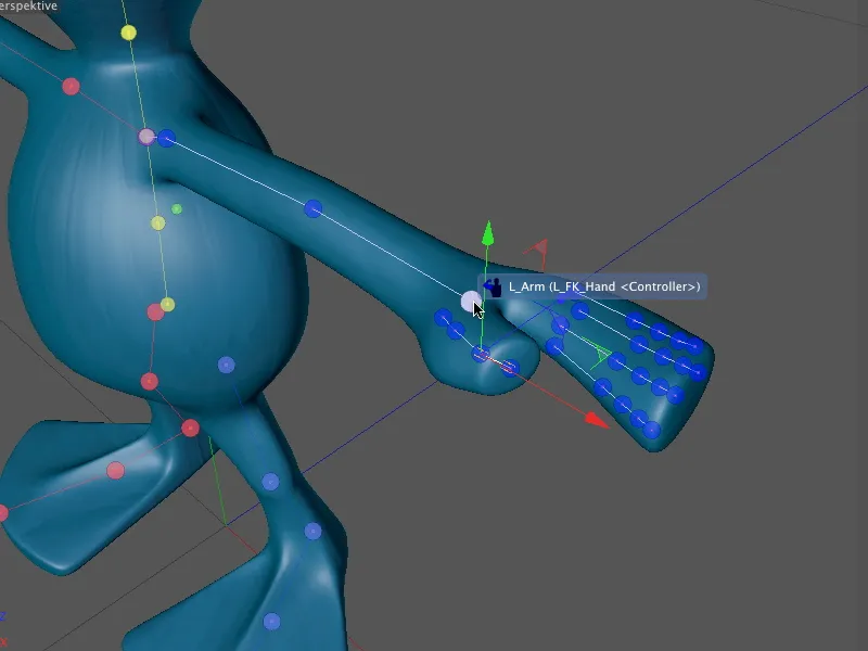
After this step, all the components for the alien character are installed and adjusted. Thanks to the character templates, the most recently added components already have control elements.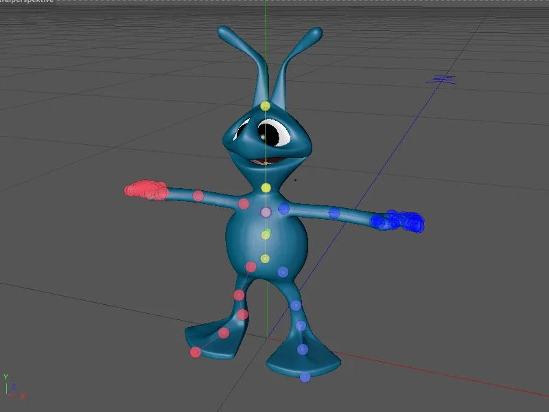
When we exit Adjust mode by switching to Customize or Animate mode, we can see the control elements attached to the arms and hands as well as the feet. But more on that later; first we need to tie the rig to the geometry.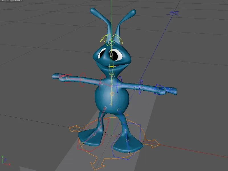
Tying and weighting the rig to the geometry
The character object also offers a convenient interface for binding and weighting the character in the form of the bind mode in the settings dialog of the character object. To bind the geometry of our alien to the character rig we have created, all we have to do is drag the polygon object of the alien geometry into the Objects field on the Bind page.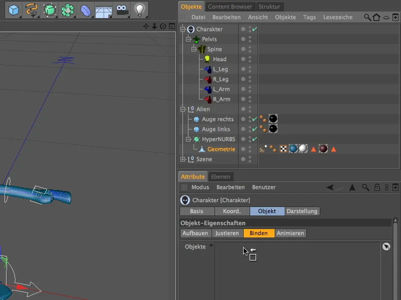
With this step, CINEMA 4D has now automatically created and assigned the skin deformer required for binding and deforming the mesh and assigned a weighting tag to the polygon object. Ideally, nothing more needs to be done here; geometry and rig are linked.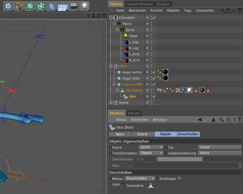
As the ideal case is unfortunately extremely rare, we check whether the weightings for the most important body areas are suitable for our character. To do this, we first deactivate the HyperNURBS object, otherwise the weightings would not be displayed in the editor. If we now select the weighting tag in the Object Manager, the corresponding joints or components are listed in the Attribute Manager.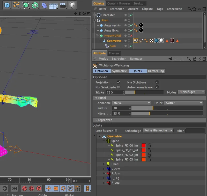
Depending on what we select in the Joints list, the editor presents the adjacent weightings in color on the geometry. If we select the top entry, all body parts appear colored accordingly.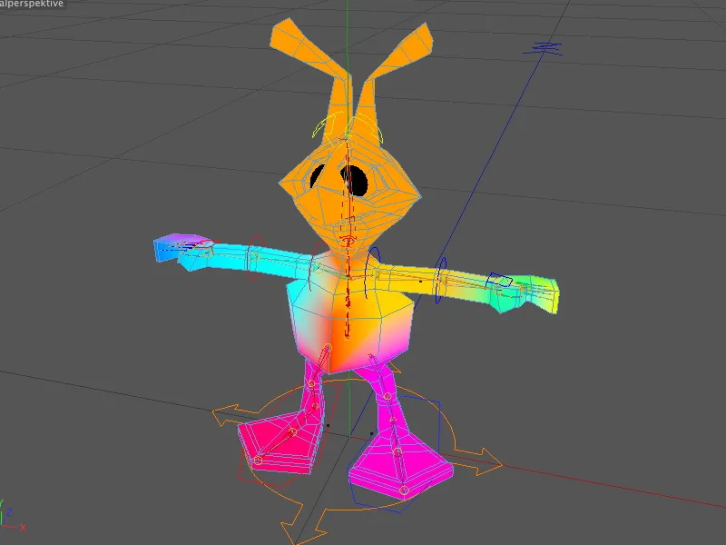
Let's check immediately whether the weighting for the head is correct. To do this, we select the Head component in the Joints list and see that the entire head including the neck appears colored - there is nothing wrong here.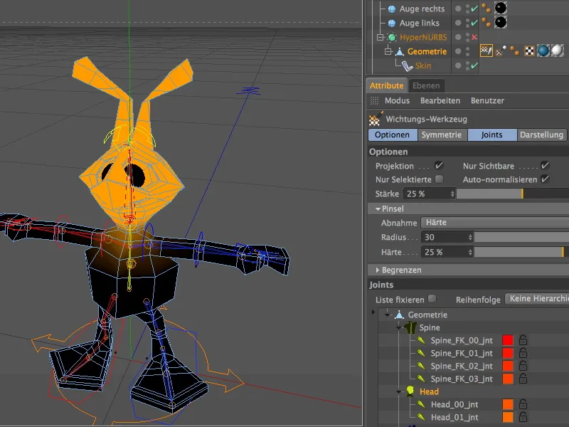
Areas with widely spaced geometry, such as the feet, are also usually critical. However, a click on the toe joints in the L_ or R_Leg component shows that there is no need to make any changes here either.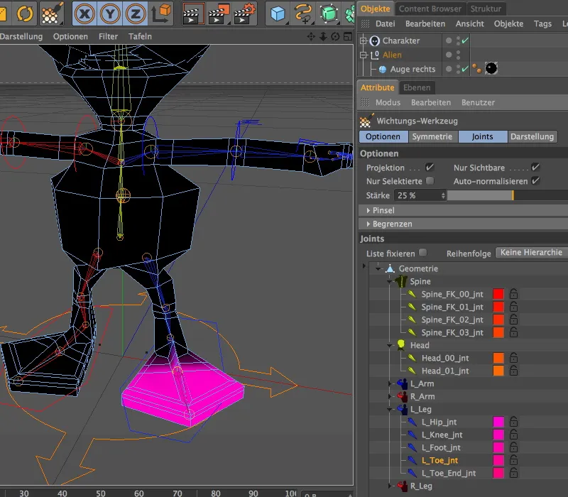
We remain in the leg component and select the top joint at the base of the leg. The coloring here clearly shows that moving the leg up to the height of the alien's chest would be noticeable. Of course, this is not desirable, which is why we have to make improvements here.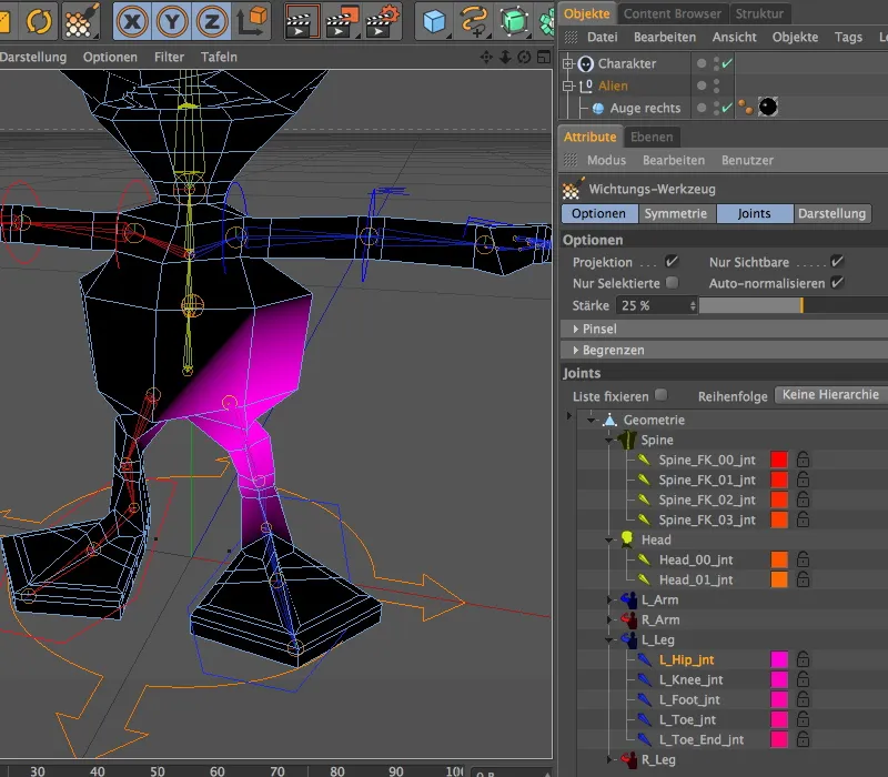
However, as the weighting tool is also active with the weighting tag, we can correct this relatively quickly. First, we activate symmetrical painting on the symmetry page of the tool's settings dialog.
The options page contains the parameters for the brush application. I usually set this to 100% hardness to ensure that all painted regions are fully covered by the weighting and only reduce this value later if in doubt.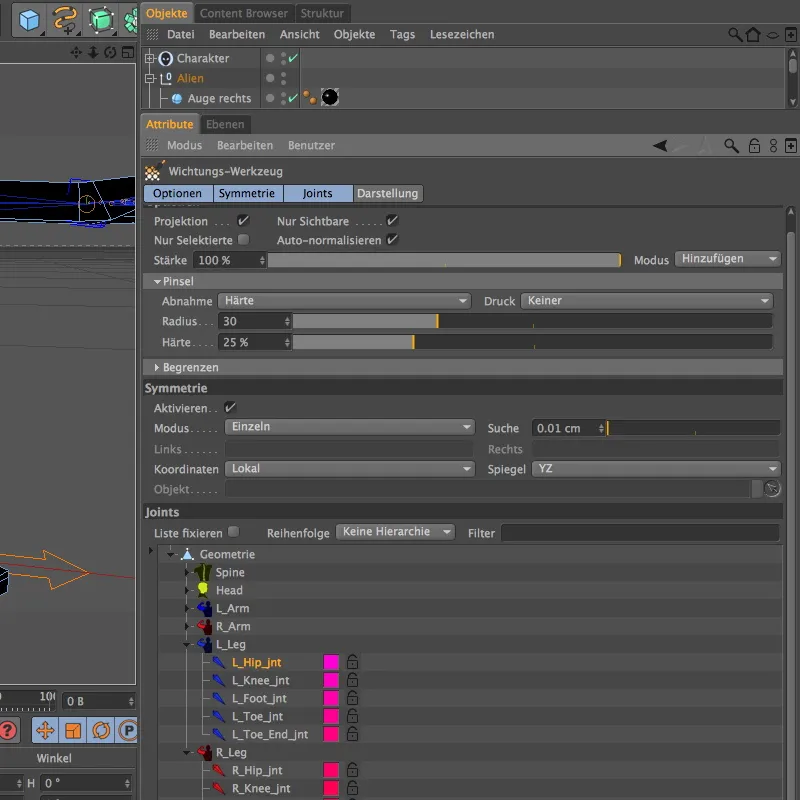
Simple painting in the editor results in positive weighting (white circle around tool), while painting with the Ctrl or Ctrl key held down erases the weighting (red circle around tool). As we want to remove the weighting on the sides of the alien's belly, we erase the weighting in the corresponding places by holding down the Ctrl key.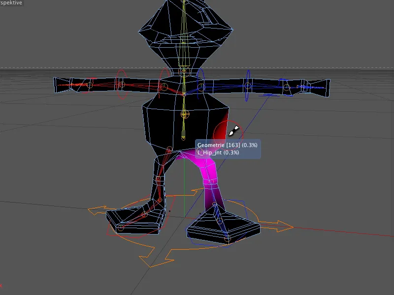
If we have erased too much, we simply release the Ctrl or Ctrl key and apply the weighting again.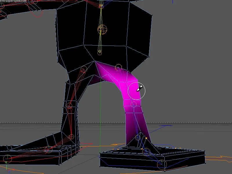
Thanks to the symmetrical painting function, the weighting of the right leg was also adjusted when editing the weighting of the left leg.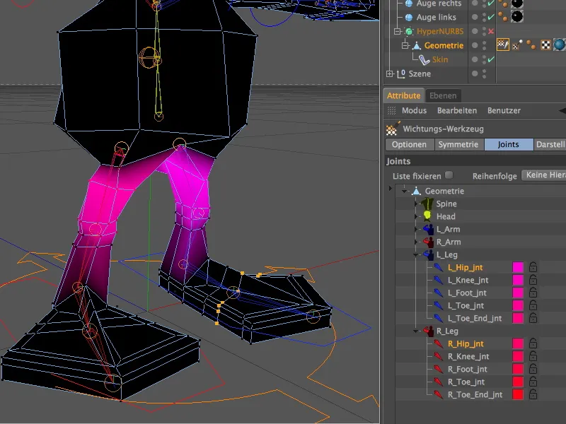
After we have changed part of the weighted alien torso when editing the legs, we have to assign these no longer existing weightings to the correct body part. To do this, we select the corresponding spine joint and use the weighting tool to generously add the affected areas of the mesh by weighting them.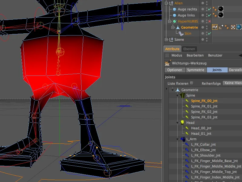
The single-color weighting display is useful for checking whether all body areas have really been assigned weights. On the display page of the weighting tool, we switch to monochrome in the Weighting colors menu. If we now select the complete joint list by clicking on the top element ...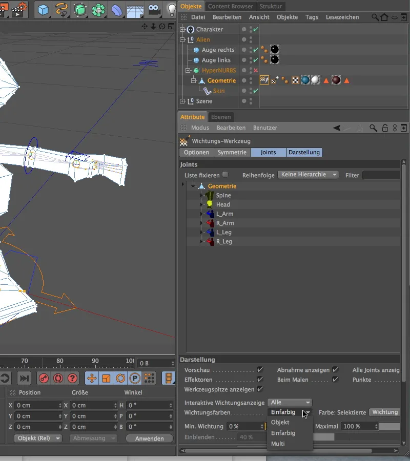
... the entire alien body should be covered with white weighting color. Otherwise we have to rework it. As the eyes are not part of the geometry, they are not covered by any weighting. To connect the eyes, we do not use weighting but a constraint.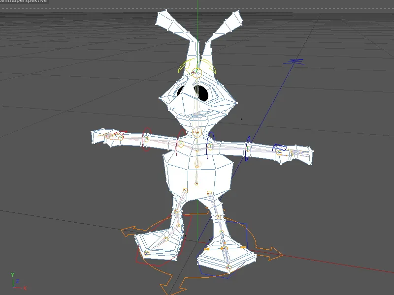
Binding the eyes using a constraint
Let's take another quick look at the objects concerned in the Object Manager. These are the two parametric sphere objects outside the HyperNURBS cage.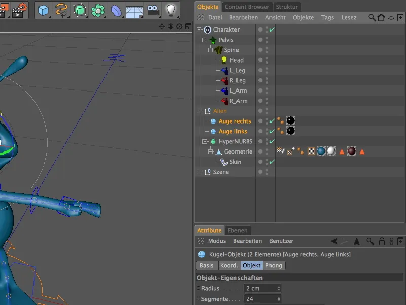
We assign a constraint tag to both objects via the Tags>Character Tags menu in the Object Manager.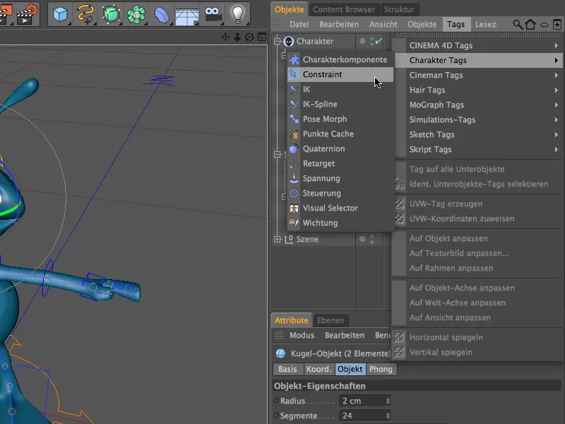
As both tags require the same settings, we select them in the Object Manager before we start working on the parameters. On the basic page of the settings dialog, we first select the type of constraint. By activating the parent object option, we make the two eyes behave as a child object of another object.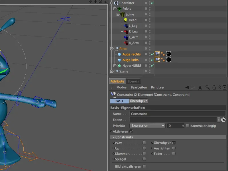
Of course, we still have to define this other object, which acts as a parent object. The joint on the alien's head would be practical so that the eyes move with every rotation or movement of the joint.
Unfortunately, instead of joints, we currently only see the components of the character object that we have created. No problem: On the display page of the settings dialog of the character object, we simply switch to the component hierarchy and we have access to the complete joint hierarchy in the object manager.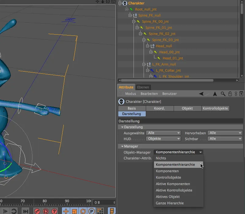
Back in the settings dialog of the two constraint tags, we expand the target field and drag in the joint Head_00_int as the target. The position and angle of the joint should be adopted so that we ensure that the P and W options are activated.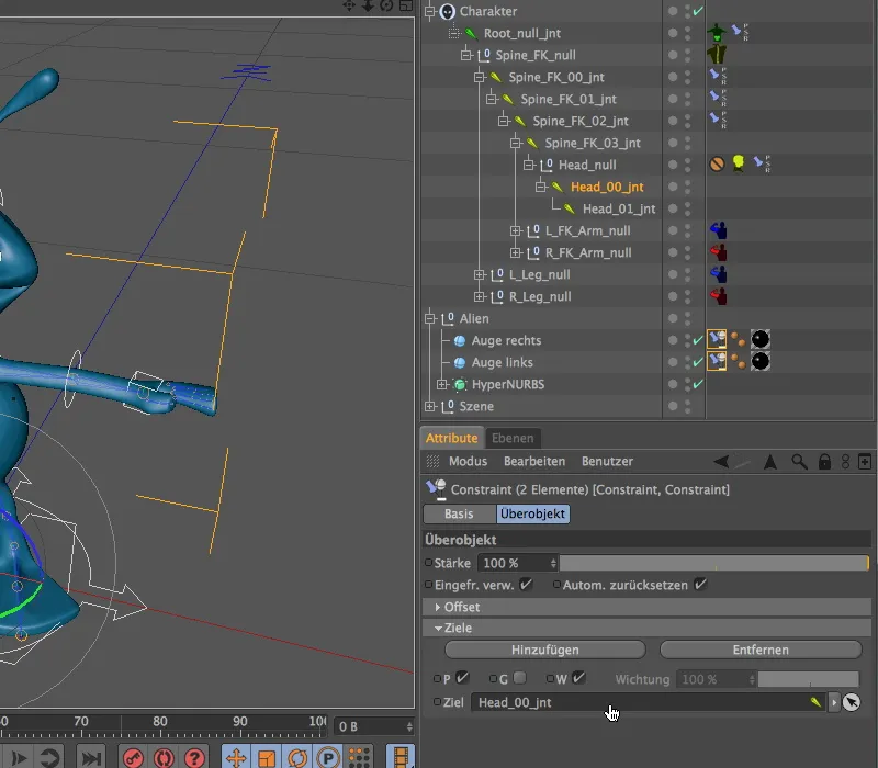
There's nothing more to do - let's test whether the eyes move with the head. To do this, we activate the head controller in the editor and rotate or tilt the head as a test.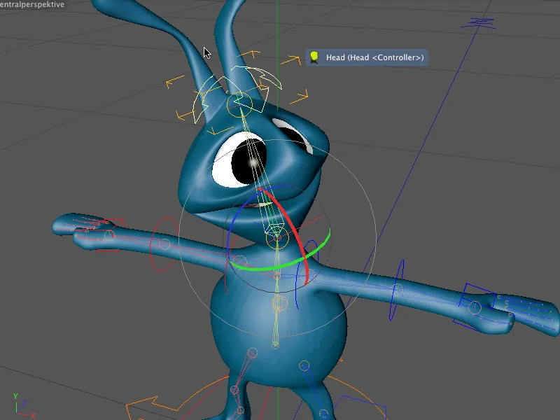
Adjusting the control objects
We can fine-tune not only the components, but also the control objects that we use to touch and animate the character. This is particularly recommended for unfavorable axis positions or angles that make simple editing unnecessarily difficult.
To adjust the control objects, we simply jump to the Adjust page of the character object in the Object tab and select the control objects as objects to be adjusted.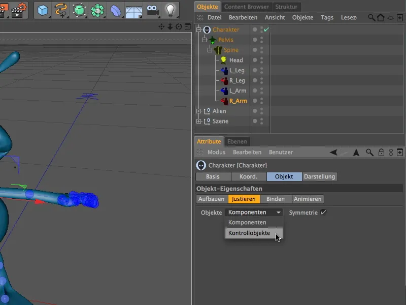
Now, when selecting the elements in the editor, we address the control objects rather than the components. In this way, we can quickly adjust the visual alignment of the alien's feet for the control objects, for example. All we have to do is rotate the control object over the rotation band using the rotate tool.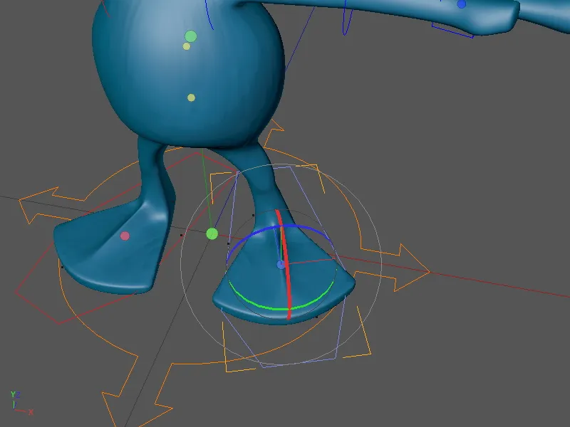
Tests with Forward (FK) and Inverse Kinematics (IK)
The alien is now fully equipped and animatable. We test the character rig a little to get a feel for the difference between the two kinematic methods.
We had used forward kinematics (FK) for the arms. If you try to simply move the hand with the control object, you will notice from the grayed-out movement axes that this is not the case with FK. Instead, the required angles must be set starting from the topmost affected element (in this case the shoulder) to the last element (in this case the hand).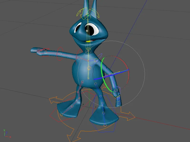
Things are different with inverse kinematics (IK). We use this method for the legs. The control object controls the alien's foot and changes the angles or positions of the upstream elements in its chain: the knee and the thigh.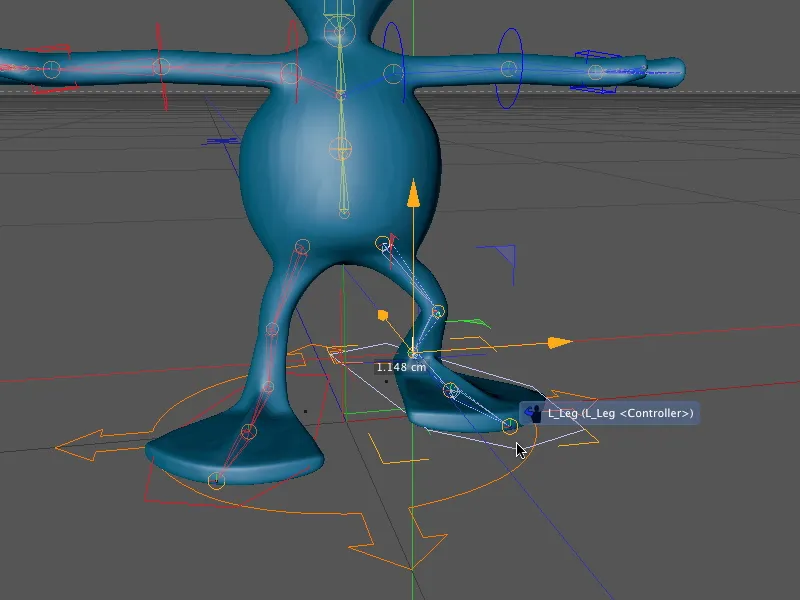
Our alien is therefore ready for animation. We can now use the control objects to breathe life into the little alien. In the next tutorial, we will literally take the next step and create individual walk cycles with this character rig.