In our example, the antennae or antennae of the alien character should move dynamically and elastically with every movement of the head. Of course, our example can also be applied to strands of hair, dinosaur tails and much more.
In the working file "PSD_C4D_R12_IK_Dyn_Start.c4d" you will find the modeled and textured alien head for collaboration.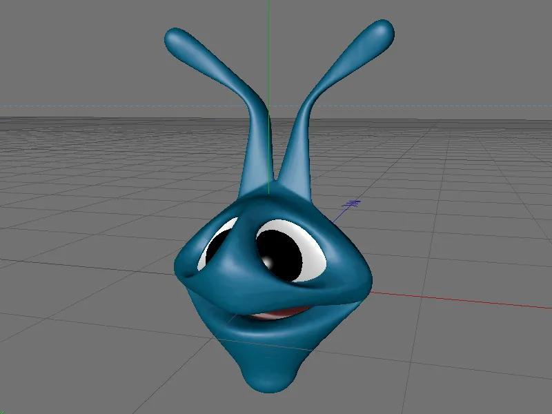
Structure of the joint framework
Our alien head consists of the polygonal head geometry on the one hand and two spherical objects for the eyes on the other. In the further course, we will bind all objects to joints either hierarchically or via weightings so that the complete head can be animated together with the antennae without any problems.
Let's start setting up the joint structure with a first joint object for the head. We can find it in the Character menu.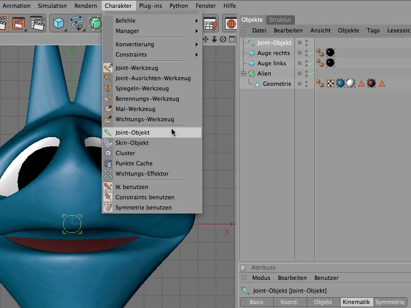
As the alien head sits exactly on the origin of the coordinate system, the head joint can remain at the zero position.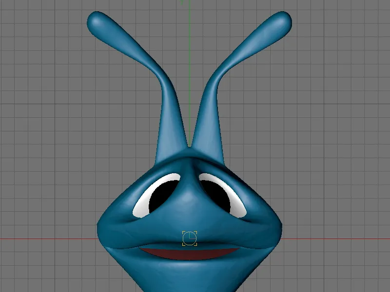
We leave the newly created joint object selected and activate the joint tool in the Character menu. In the settings dialog of the joint tool, we deactivate the creation of a parent root-zero object. We will create it ourselves later in order to better understand what function it actually has in a joint structure.
So that we can work symmetrically, we expand the Symmetry area and use the Draw option on the world YZ level. We will draw the joints on this plane or in this view.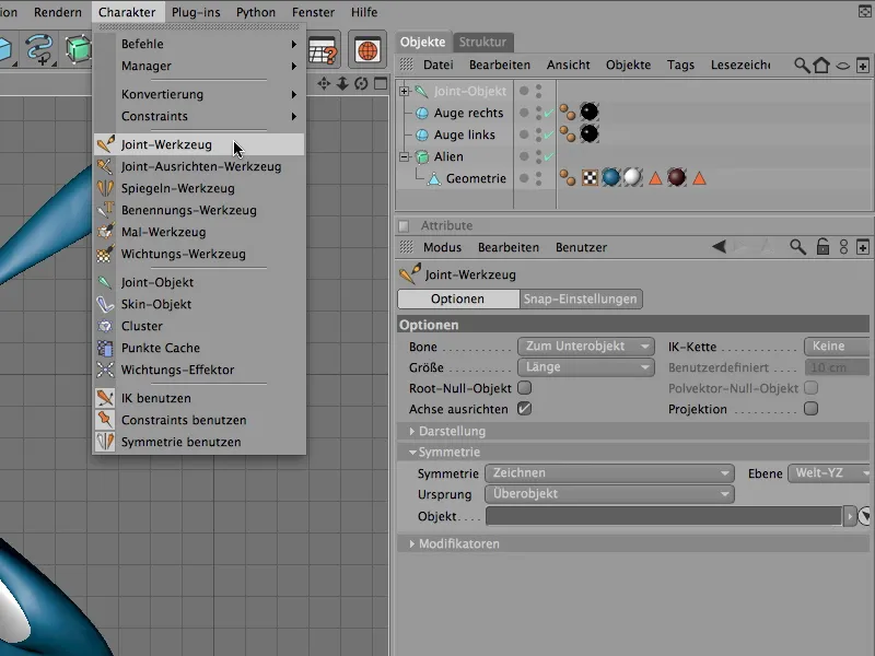
If we now click in the view with the joint tool activated and the Ctrl key pressed, joints subordinate to the head joint will be created automatically and symmetrically.
We decide on one of the two sensors or antennas and place the first sub-joint directly at the base of the sensor on the head. CINEMA 4D sets the joint for the other sensor automatically thanks to activated symmetry.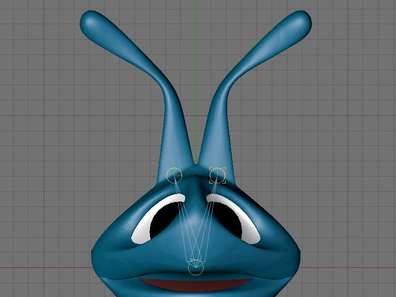
We now create a joint chain at the positions shown in the illustration by clicking and holding down the Ctrl key. The joints should be a little closer together where it is more delicate. We should not economize with the joints, because only at these joints can a deformation or bending of the geometry take place at all.
Once we have created all the joints, we find the joint hierarchy shown in the illustration in the Object Manager. The head joint object has a total of two joint chains as sub-objects - one chain for each sensor or antenna.
To adjust the position of the joints in pairs in the side view, we select a pair of joints in the Object Manager and move the joints along their z-axis in the geometry.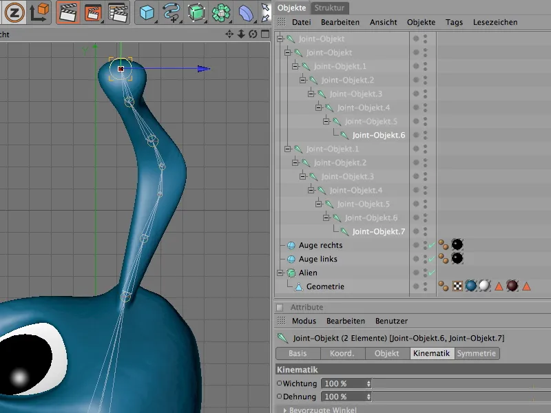
The joint structure for the animation of the sensors or antennas is now complete. Unfortunately, it does not yet have a reference to our alien head that would allow us to animate the head.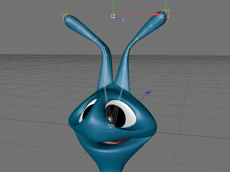
This is only possible once we have linked the joint hierarchy to the geometry. To do this, we first select all joint objects and the polygon object of the alien geometry via the object manager.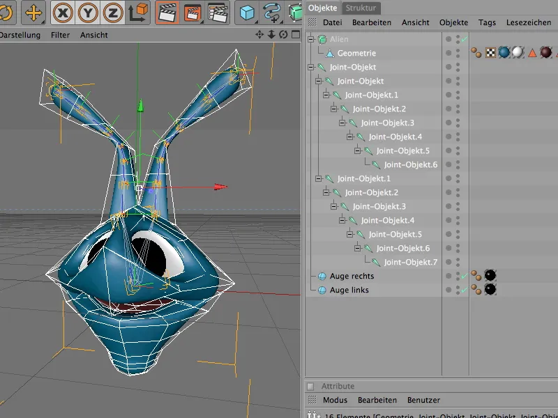
We now connect the joint hierarchy with the polygon mesh using the Bind command from the Character>Commands menu.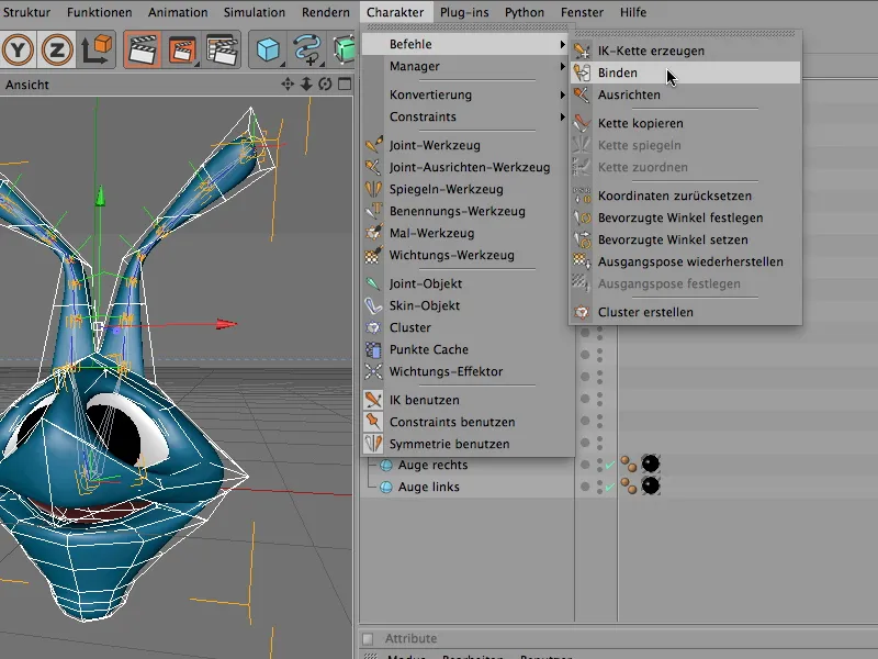
What has the Bind command done? The polygon object of the alien geometry now has a weighting tag whose settings dialog contains all the joint objects that can influence the geometry of the alien head. This automatic weighting is based on the position of the joints in relation to the geometry and is a good starting point.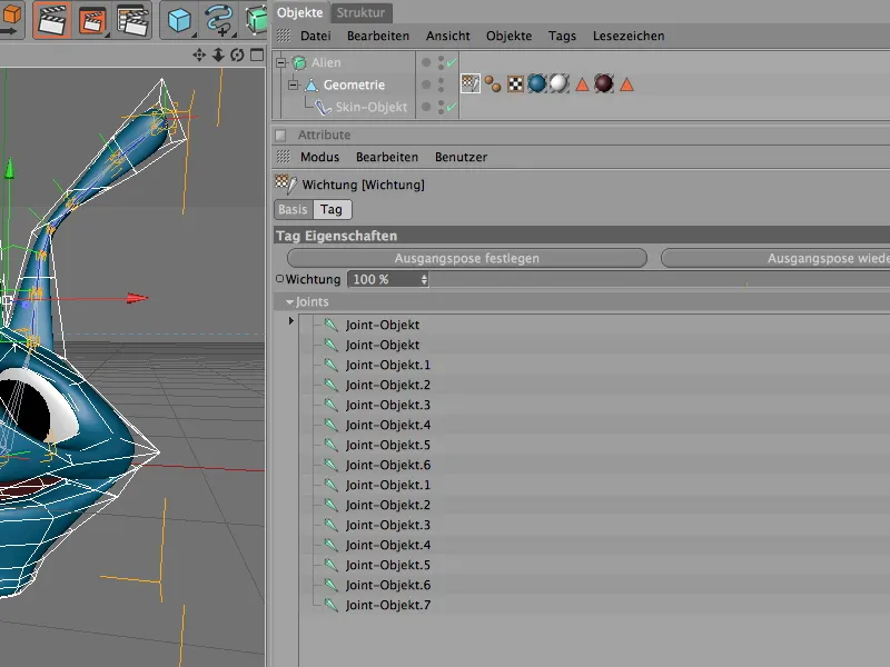
Weighting the joints
However, this weighting is rarely perfect, so a little reworking is required. To get an impression of the existing weightings, we first deactivate the HyperNURBS cage function via the Object Manager. The weightingtool shows the weightings on the geometry with an unsmoothed polygon mesh. For a complete overview, we first select all joint objects with the geometry in the Object Manager.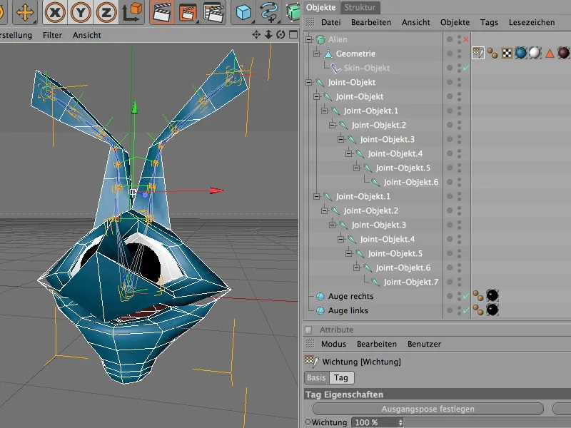
The weighting tool can be found in the Character menu. Once we have activated it, the geometry of the alien head is colored. Each joint has its own color, which indicates its influence on the geometry.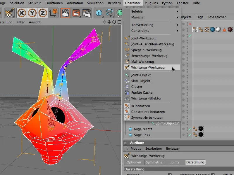
To be able to assess the joints and their influence on the geometry individually, we simply have to select the respective joint in the Object Manager. All areas of the geometry not covered by this joint remain black.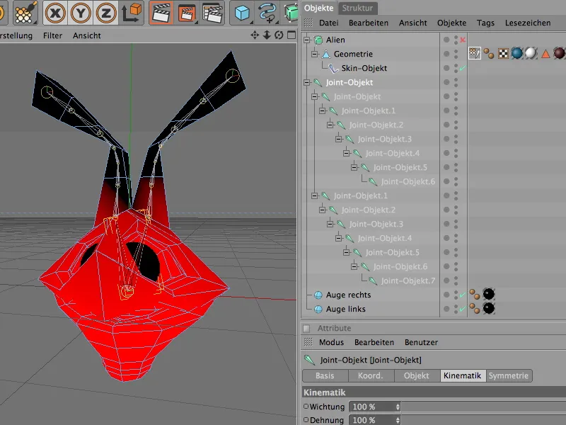
On the head joint, it is noticeable that the tip of the nose is not 100% in the joint color. We can use the weighting tool to prevent any incorrect behavior in the event of deformation by using the weighting brush to increase the weighting for the joint.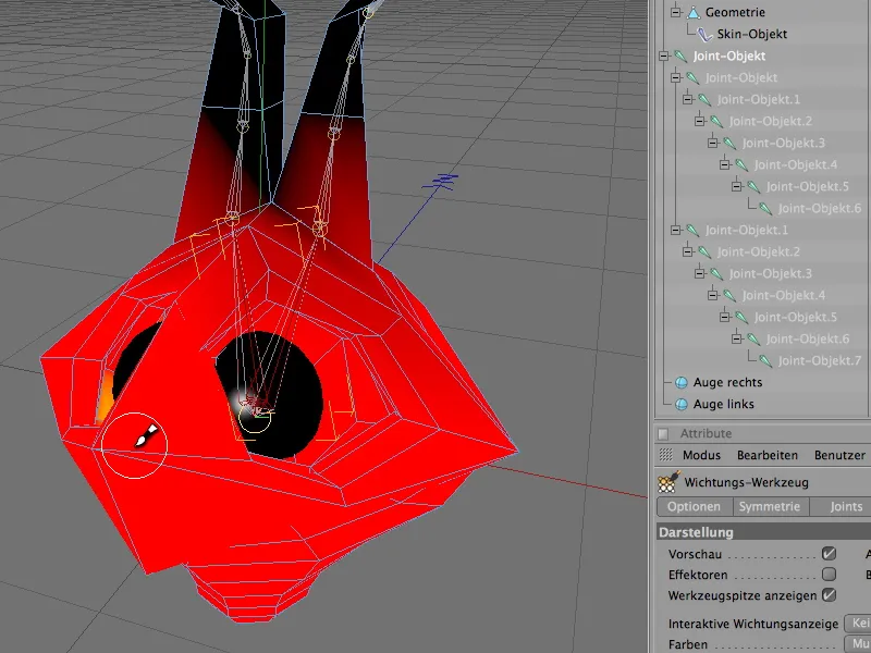
There is also a little too much influence on the head geometry at the transitions to the probes or antennas. To reduce existing weightings, we use the weighting tool with the Ctrl key held down.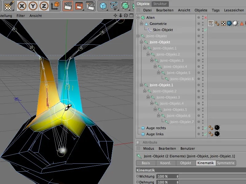
To complete the weighting work, it is advisable to select all joints again via the Object Manager, set the weighting color to monochrome and check whether the entire geometry has a weighting. As can be seen in the illustration, the entire alien head is colored white, which tells us that all parts of the geometry are weighted.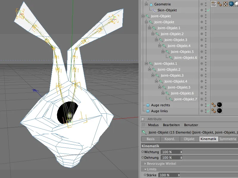
The spherical objects of the eyes were left out of the weighting. To ensure that these objects also move when the head is rotated or moved, we simply assign them to the head joint in the Object Manager. If the head joint is now rotated, for example, the eye objects follow the orientation of the head due to their subordination.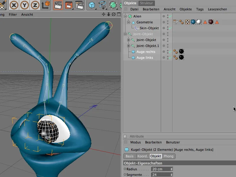
Now it is high time to check the joint structure and the weightings it contains in practice. To do this, we select the head joint and rotate it along the y-axis using the rotate tool. The complete alien head should follow the movements of the head joint without any problems.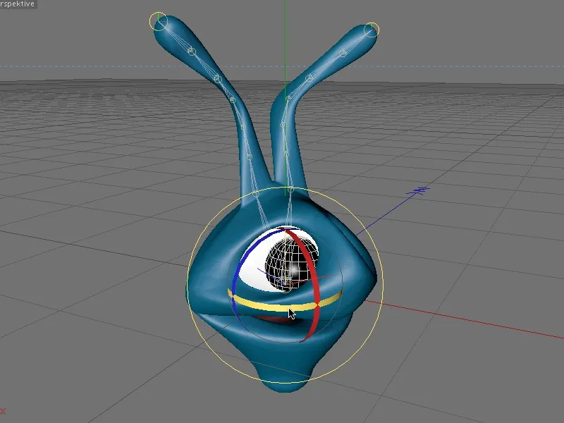
Integrating the inverse kinematics with dynamics
Now that the joints are acting on the respective areas of the alien head as desired, we can take care of the animation of the sensors or antennas using inverse kinematics (IK). To do this, we need to define the two joint strands for the sensors and antennas as an IK chain.
We select these two joint chains in the Object Manager - please note that the head joint is not included!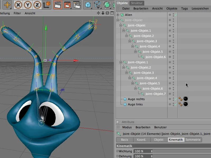
Once again, CINEMA 4D offers a special command called Create IK Chain, which automatically processes the selected joint chains into IK chains. We can find it in the Character>Commands menu.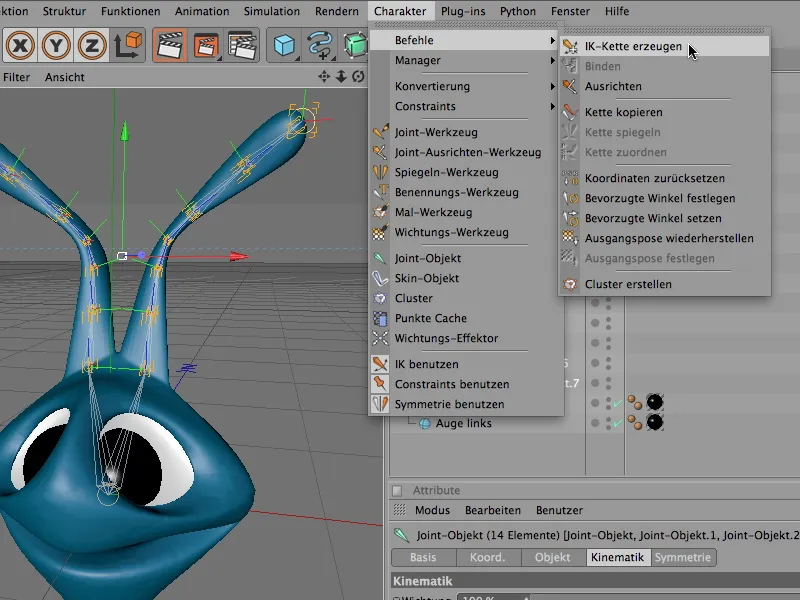
We use the Create IK chain command and check what has happened to our joint chain. The two joints at the start of the head were each assigned an IK tag. The start and end of the IK chain were automatically stored in this tag.
We also find two new null objects as target objects in the Object Manager. These two targets are named in the same way as the ends of the join chain and allow us to animate the entire IK chain using these simple control targets.
We actually want to control the movements of the sensors or antennas fully automatically using dynamic properties. However, it doesn't hurt to keep these two target objects, as the sensors or antennas will always align themselves with the targets after each movement and deformation and thus position themselves automatically.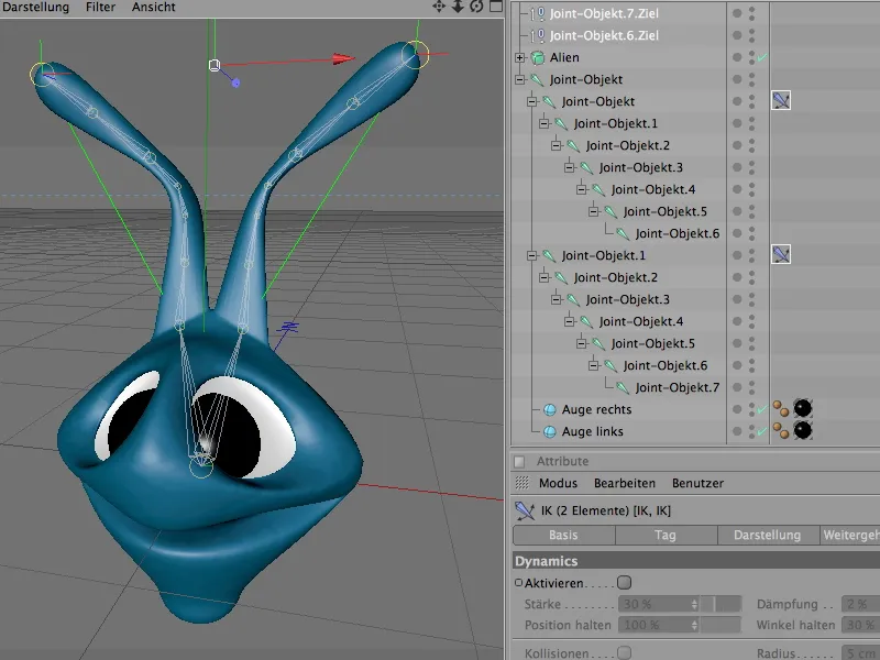
A look at the settings dialog for the IK tags shows us how the ends or targets of the IK chain are defined. We can keep these parameters in the Tag area; we are now more interested in the Dynamics settings.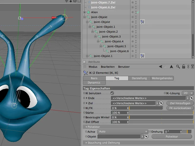
To do this, we switch to the Dynamics tab and first activate the Dynamics option. Now the sensors or antennas can already react to influences such as gravity or movement.
To ensure that the sensors do not simply hang limply, but rather appear elastic and resistant, we reduce the Dynamics strength to approx. 40-45% and drastically increase the damping to approx. 70%. To make the sensors try even harder to return to their original state, we increase the Hold angle parameter to approx. 40-45%.
At this point, I can only invite you to continue experimenting with the parameters. You will quickly learn how the individual settings affect the entire chain of inverse kinematics - and of course it's fun too.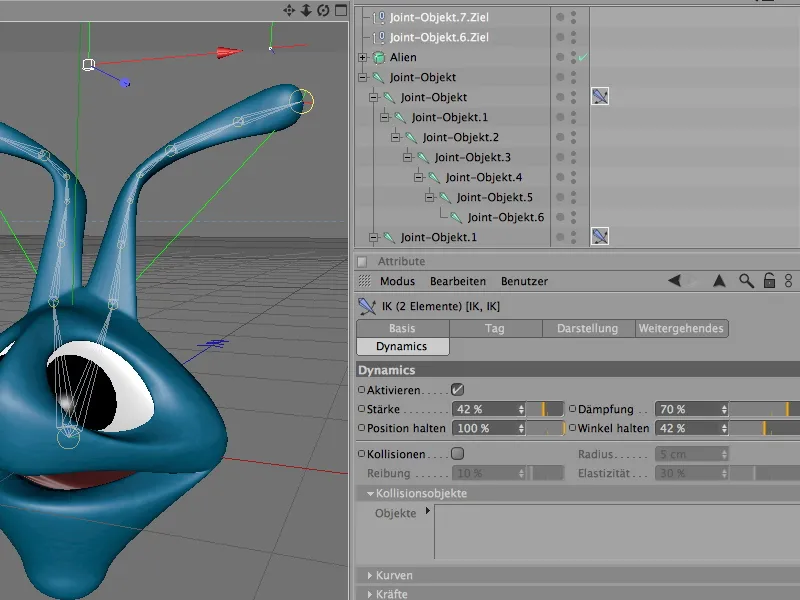
Because the two outsourced target objects are not affected by the dynamic animation of the sensors or antennas, we have to teach the IK that these targets should also be moved. Otherwise, the sensors would very quickly become entangled with each other during a fast rotation.
The Advanced tab in the IK tag offers us a very elegant function for this. We simply activate the Move target option here and the two target objects automatically move with every movement.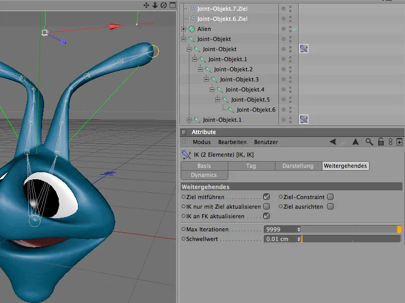
The inverse kinematics functionality of the sensors and antennas is now also complete. Let's tidy up the Object Manager a littleby renaming the target objects and the joint chains appropriately.
The head joint is currently still used as the handle for the animation of the alien head. Unfortunately, this joint is relatively unwieldy because it rotates in space due to its subordinate joint chains.
However, we actually need a "clean" starting position at the angles so that the rotation and movement of the alien head can take place for us without unwanted pre-rotations.
This is where the root-zero object, which we briefly encountered at the beginning, comes into play.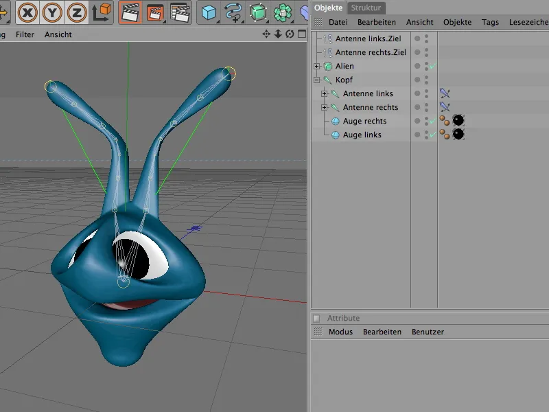
It provides us with a completely new, virgin coordinate base. And to ensure that the entire IK chain is taken into account, we simply have to subordinate it to the root null object.
First, however, we create the fresh null object via the Objects menu. Because the head joint is in the null position, we do not even have to reposition the new null object.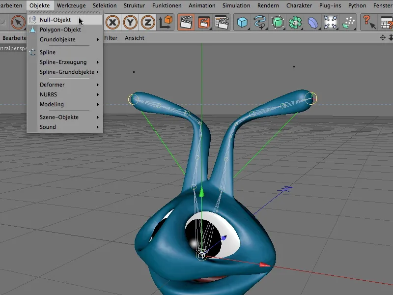
We rename this new null object to Root and assign the complete joint hierarchy to it via the Object Manager.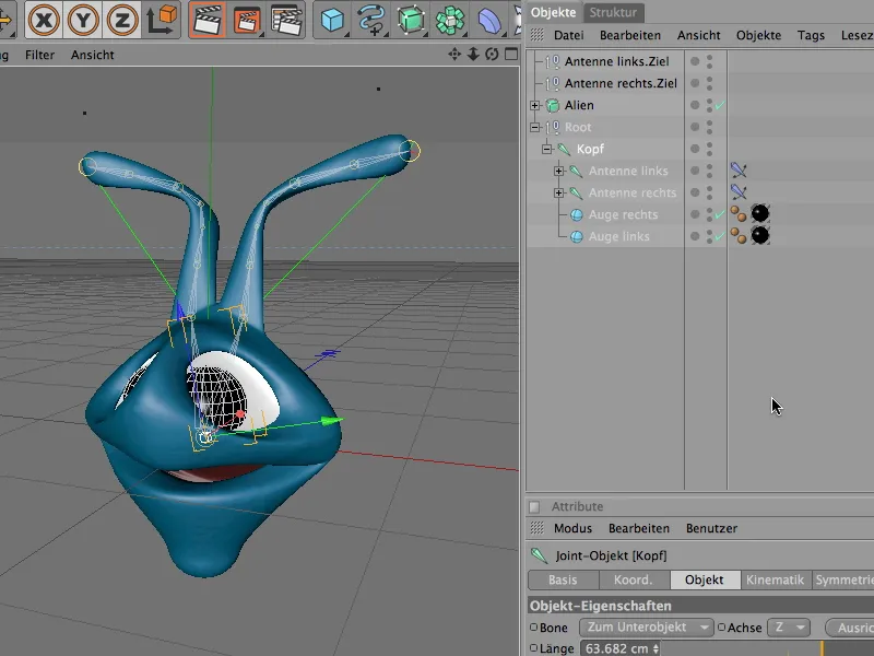
Now we can press the play button and rotate and animate the alien in all directions by rotating the root null object. The antennae are dynamically controlled by gravity and our movements.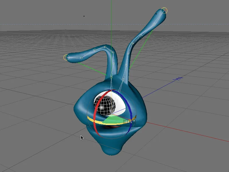
The root-zero object is therefore a practical helper when animating a joint hierarchy. When creating a joint structure, at least the main joint (usually the hip) is assigned such a superordinate null object. For this to happen automatically, we only need to activate the Root null object option in the settings dialog of the joint tool.


