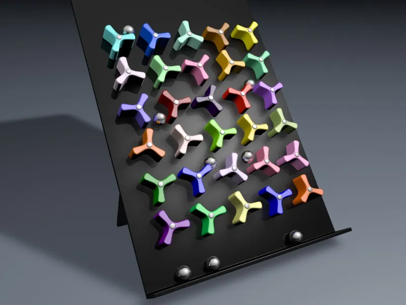
So that we can concentrate fully on working with Dynamics and MoGraph, you will find all the other components of the scene in the working file "PSD_C4D_R12_Dyn_RigidB_Konnektoren_Start.c4d".
A three-bladed rotating wheel and a sphere object should suffice; the rest is done with MoGraph clones or a particle emitter.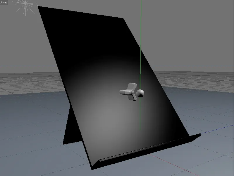
Building the scene with MoGraph clones
The three most important objects in our scene are the sphere, the rotating wheel and the inclined plane on which the spheres will later roll downwards. With the exception of the wings of the rotating wheel, all objects already have a material. If you want, you can adapt the scene to your own ideas using other materials.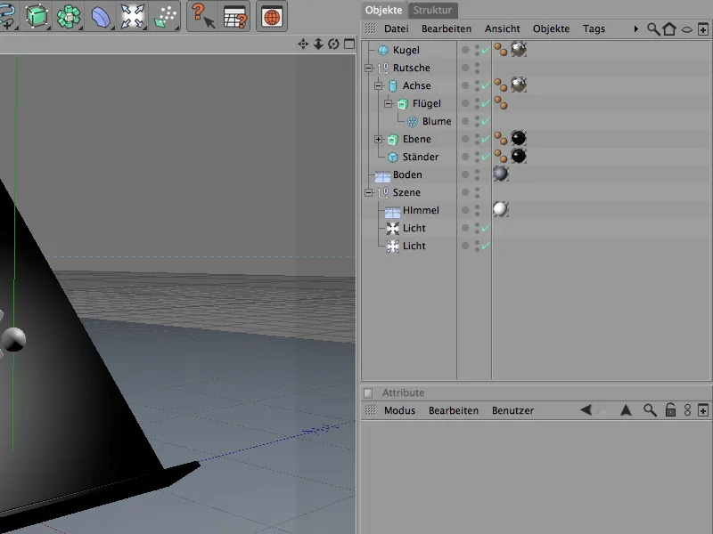
For the balls, we use a simple, parametric ball object that will be cloned later. The radius of 7 cm matches our rotating wheel and the plane, the lower edge of which should later catch the spheres as well as possible.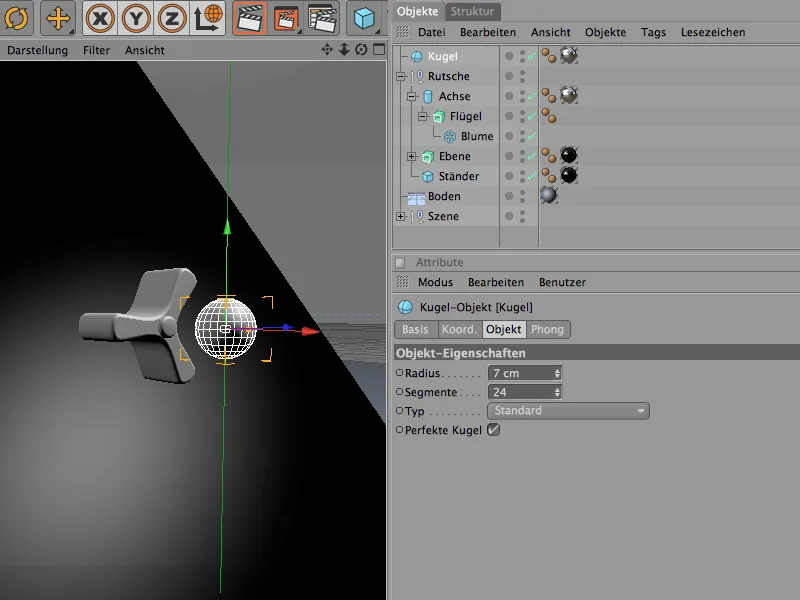
The rotating wheel is created by extruding a Blum spline object with an Extrude NURBS generator. The number of blades was reduced accordingly for the three wings of the rotating wheel. The inner radius is just large enough to accommodate the inserted axle (a simple cylinder object).
If you like, you can also experiment with four or even five blades.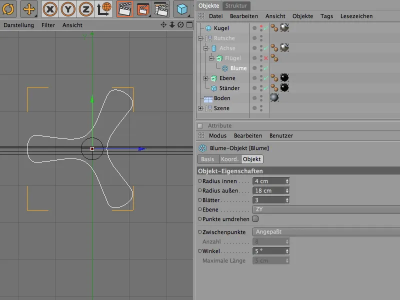
The Extrude NURBS generator ensures the three-dimensional shaping of the given Blum spline object. The depth of the rotating wheel is defined via the displacement parameter.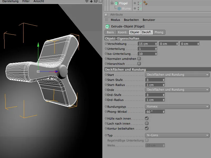
The previously mentioned cylinder object is superordinate to the rotating wheel. It will later act as the rotation axis of the connector for Dynamics.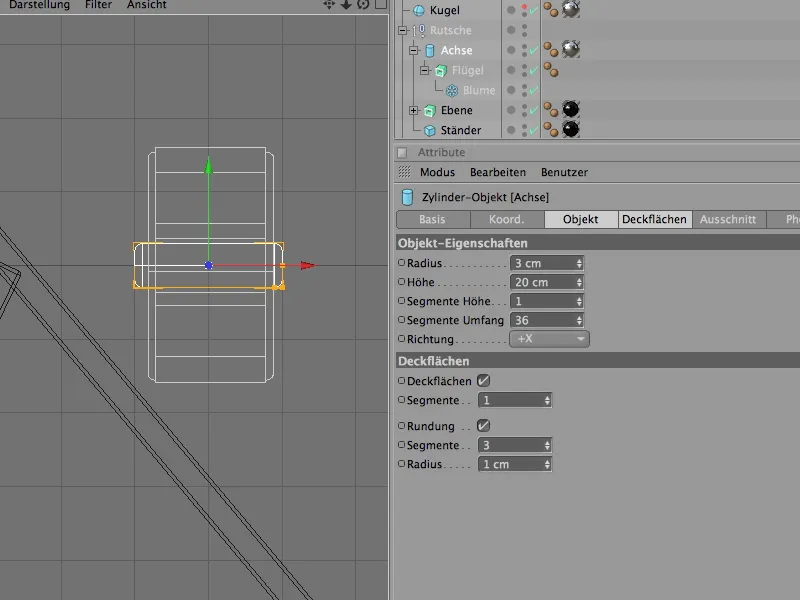
Finally, we come to the plane, which is actually also an ExtrudeNURBS object that transforms a predefined spline path (in this case an L-spline) into a three-dimensional object through extrusion.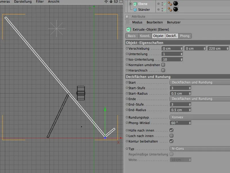
So much for the structure of the start scene. We start with the spinning wheels and use MoGraph to get enough copies or clones for our plane.
So we get a clone object from the MoGraph menu.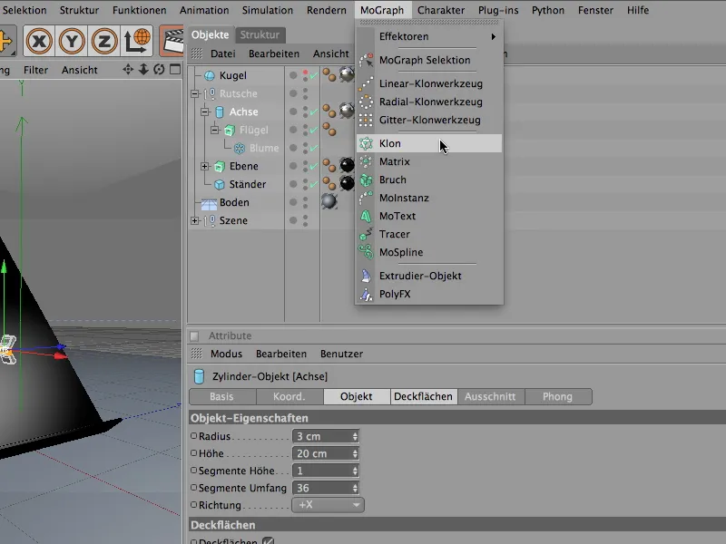
In the settings dialog of the clone object, we first set the mode to grid.
In the associated parameters, we can now specify the number of clones and the size of the resulting grid. Because the grid should consist of one layer in the x-direction, we leave this number of copies at 1, in the y-direction we create 6 or 5 clones in the dimensions shown.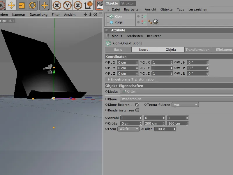
So that the clone object also knows which objects it should duplicate, we place the complete hierarchy of the rotating wheel in the object manager as a sub-object in the clone object. As desired, the clone object produces the rotating wheels in the grid-shaped arrangement.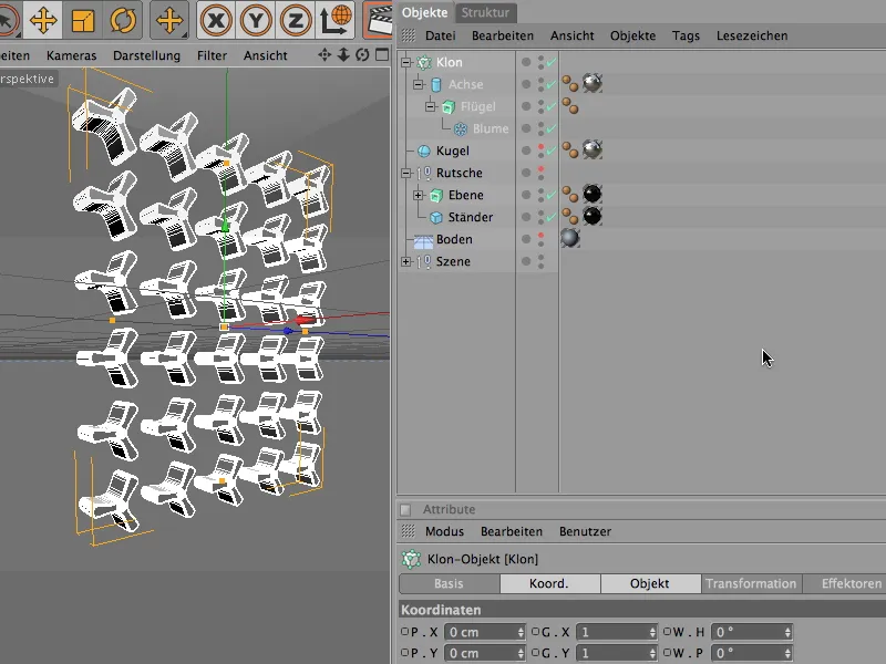
We now place the cloned rotary wheels on the plane. As the rotation angle of the plane is 40°, we also adopt this value for the clone object , here as a banking angle of - 40°.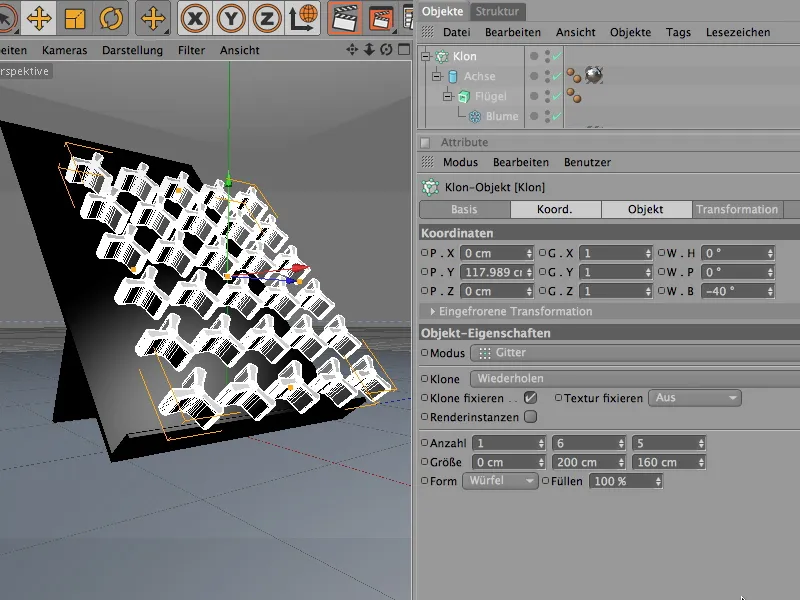
To place the clone grid with the rotating wheels exactly on the plane, it is best to switch to the side view, activate the global axis alignment and move the rotating wheels along their axis close to the plane. As the axis of the wheels protrudes slightly to the rear, it can easily dip into the plane.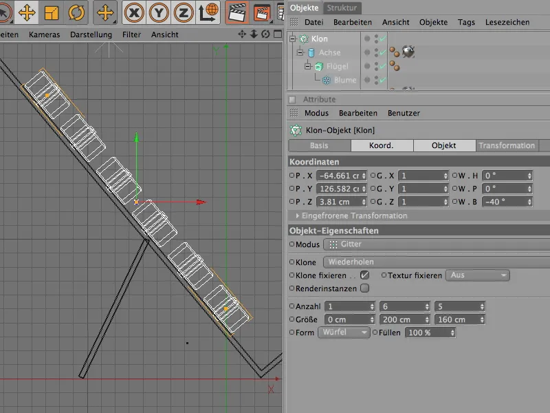
The rotating wheels would then be installed and can move back into the "slide" group as a sub-object. What is still rather annoying at the moment is the all too perfect, completely identical alignment of the rotating wheels. To put an end to this monotony, we integrate a random effector.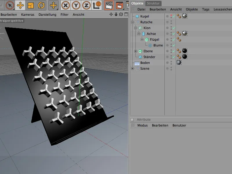
We can find it in the MoGraph>Effectors menu and bring it into our scene. If you select the clone object in the Object Manager before calling up the random effector, the effector is automatically assigned to this clone object.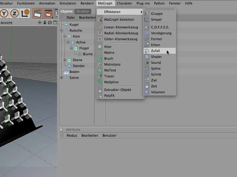
In the settings dialog of the random effector, we will first of all take care of the random rotations of the wheels. To do this, we open the Transform field in the Parameters area and activate the Angle option for the transformation. To rotate the wheels by their pitching angle, we enter a value here. An angle of 60° gives the wheels enough room to rotate.
Because we also want to use the random effector for the color of the wheels in their material, we also open the color field and activate the color mode. In the higher-level effector parameters of the random effector, we can experiment with the random values via the start value. More on this later.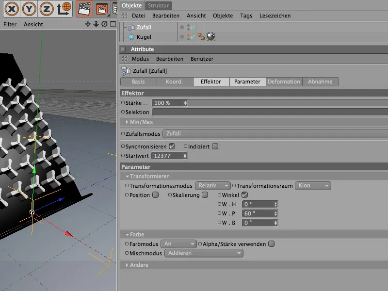
In the editor view, the changes caused by the effector can normally be observed immediately. Provided that the random effector was assigned to the clone object when it was created. If not, we can do this quickly in the settings dialog of the clone object via the Effectors area. From the Object Manager, we drag in all the effectors that should or may affect the clone object.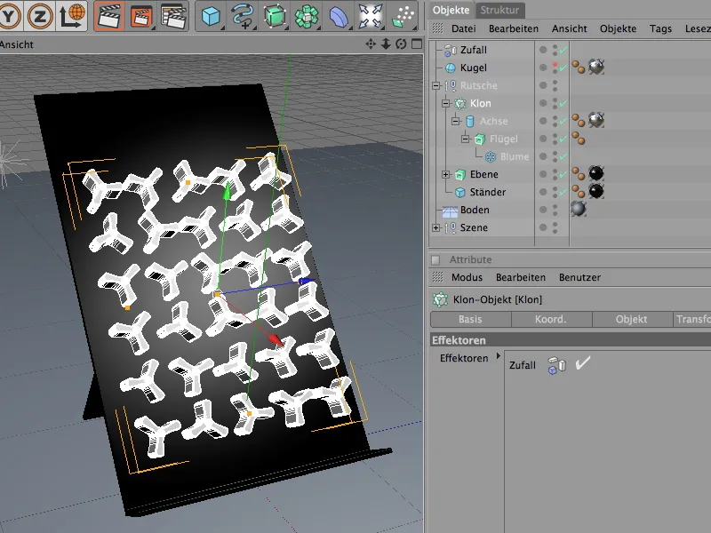
To spice up the scene a little, we can make the dials different colors. The random effector will save us a lot of work. First, however, we create a new material, either via the menu command with the same name in the material manager or by double-clicking on a free space in the manager.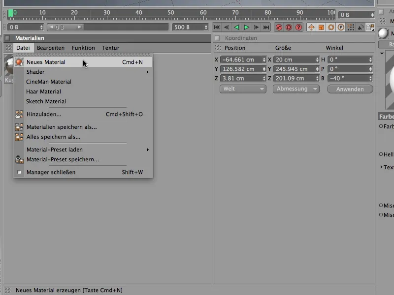
In order for the random effect to influence the color in the color channel, we create the color shader from the MoGraph submenu in the texture's arrow button menu.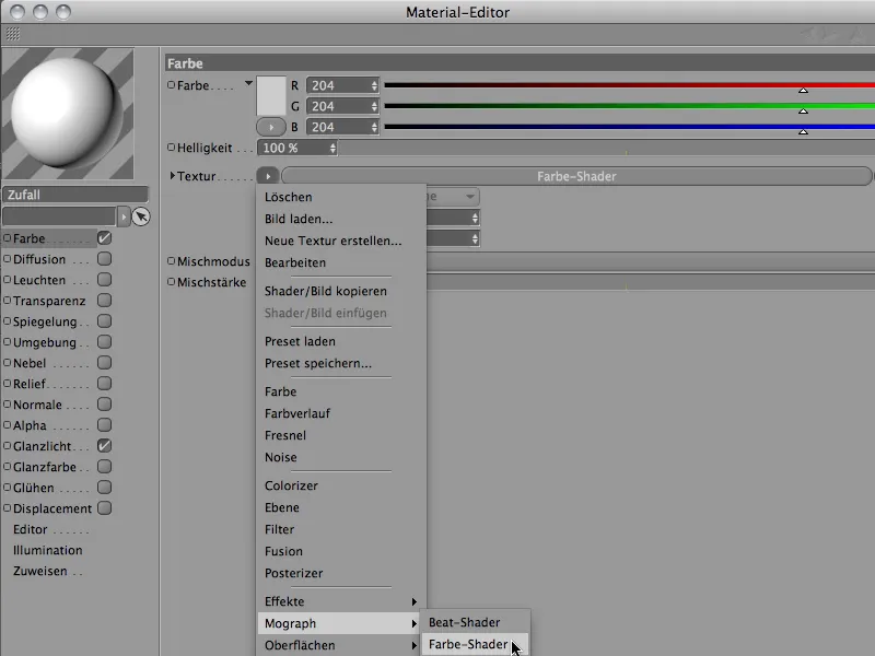
After clicking on the color shader button, we find ourselves in the fairly clear settings dialog for the color shader. Here we make sure that the Color option is selected for the channel.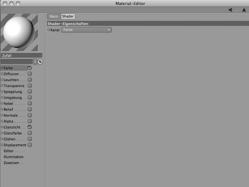
Now we just need to assign the material for the wheels to the Extrude NURBS object of the wing. To do this, we drag it from the Material Manager onto the sash object of the rotating wheel in the Object Manager. If you don't really like the color combination for the rotating wheels yet, you can change the start value parameter in the random effector until you like the randomly selected colors.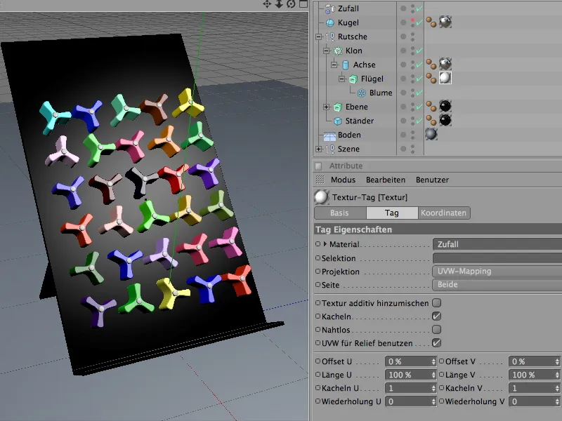
Setting up the dynamics system with collision objects and rigid bodies
Now the scene has been prepared to such an extent that we can integrate the elements involved in the simulation into a dynamics system. Let's start with the pure collision objects, i.e. objects such as the plane and the floor, which are not dynamic but are only involved in the system for collision detection.
Both are defined as collision objects via the Simulation>Dynamics menu using the Create collision object command.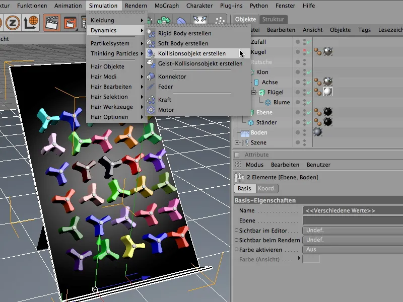
The command assigned the selected objects a Dynamics Body Tag, in whose settings dialog the dynamic functionality was automatically deactivated for us and collision detection was activated. In the collision area, we set the elasticity and friction to 30% each so that the impacting balls do not bounce upwards unintentionally, but roll out slowly.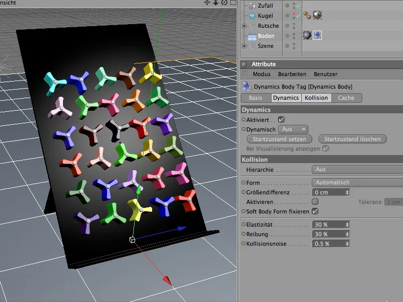
The situation is slightly different for the second collision object, the slide plane. Here we need the static mesh as a collision shape in the collision area. Due to the L-contour of the slide plane, this guarantees that the shape of the object is also used correctly for the calculation of the collision. The friction parameter can be slightly higher for the plane so that the balls do not roll too quickly through the turning wheel course later on.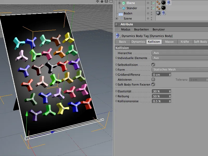
In contrast to the pure collision objects, the rotating wheels actively participate in the dynamic events. As they are also rigid bodies, we define them as rigid bodies. To do this, we select the wing object from the clone structure hierarchy and define it as a rigid body using the Create Rigid Body command from the Simulation>Dynamics menu.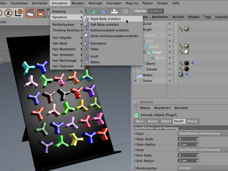
The behavior of the rotating wheels in the event of a collision is also different. To avoid unwanted unrest in the clone grid before a real collision takes place, we set the triggering of the dynamic property to On collision in the settings dialog of the Dynamics Body tag.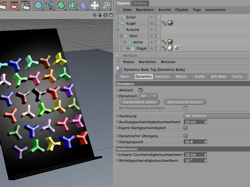
The collision page is about the detailed adjustment of the collision properties. Here, the Automatic collision shape setting ensures that the best possible collision envelope is used for the particular shape of the wheels. Because we do not want the impacting balls to bounce far away after the collision, we reduce the elasticity to 20%. The high friction value of 80% also ensures that the balls lose energy every time they come into contact with the rotating wheels.
The use of a separate mass is always advisable when colliding objects of different masses have to be coordinated. Since the balls of the spinning wheels do not differ in size from the spinning wheels, but differ greatly in mass, we specify a mass of 8 here. The rotational mass of 80% ensures that the wheels are somewhat easier to turn.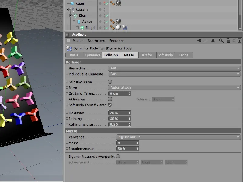
In order to have a little more influence on the prevailing energy and to ensure that the simulation comes to rest within a reasonable period of time, we additionally dampen the forces acting on the wheels.
On the forces page of the settings dialog, the spinning wheels are assigned a linear damping of 60% and a damping of the rotation of 80%. Despite the strong impact of the balls, this will allow the wheels to stabilize relatively quickly.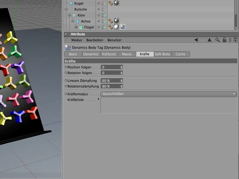
Functional expansion of the rotary wheels with connectors
If you were to start the simulation by clicking on the play button, the wheels would fall and slide down the plane without a sound at the first collision. Although they are visually stuck in the plane with their axis, the axes do not play any role in our simulation. We use the so-called connectors to create a connection between the rotating wings of the turning wheels and the axis. They can be found in the Simulation>Dynamics menu.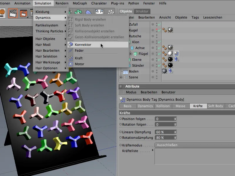
In principle, the connector does not care where it is located in the elements or hierarchies in the Object Manager. However, in order to maintain the logic in our scene, we combine it functionally correctly with the cylinder object of the axis. For a better overview when integrating the connector, we temporarily deactivate the production of clones via the Object Manager.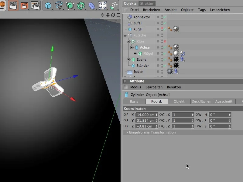
If the connector is to take on the role of a rotary axis, it first needs the correct position and orientation, in our case the coordinates and angle of the cylindrical axis. This process is simplified by the Apply command from the Functions menu, which we call up when the connector is selected.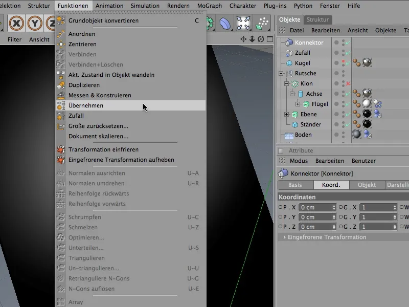
In the settings dialog of the Apply tool, we first specify the cylinder object of the axis as the data donor. To do this, we drag it from the Object Manager into the corresponding Transfer from field. As we are going to fine-tune the connector itself, we can apply all the parameters at this point by clicking on the Assign button.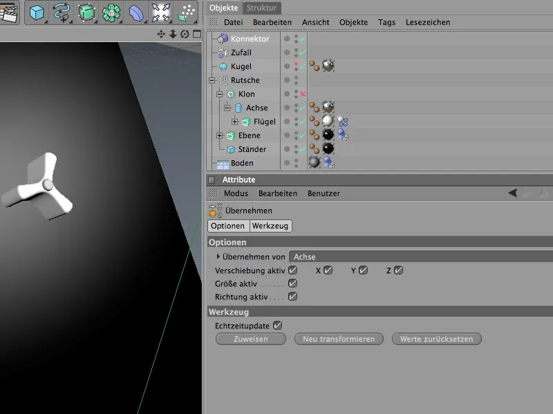
We select the connector via the Object Manager and adjust its alignment to the rotary wheel. As can be seen in the illustration below, the heading angle should be rotated by - 90° and the pitching angle (according to the slope of the plane) by 40°. On the display side, we can reduce the size of the connector so that it fits better with the rotating wheel.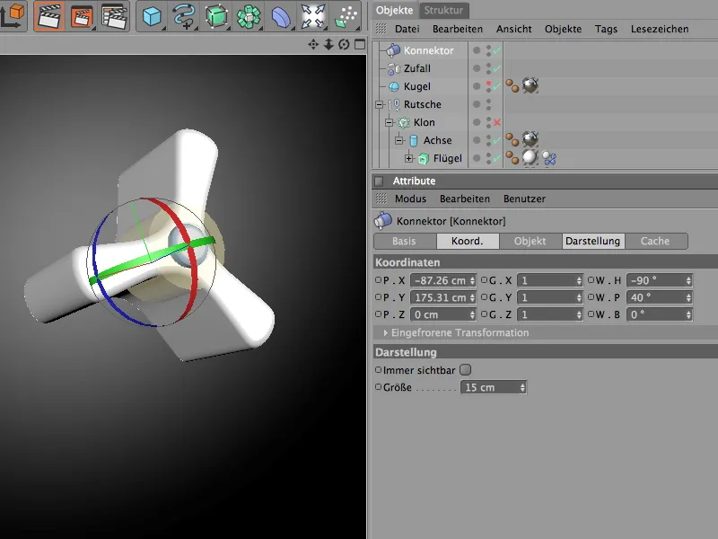
We define the actual functionality of the connector on the object page of the settings dialog. The hinge type holds the connected objects to the axis and only allows rotation around the specified reference axis. As our example with the impeller and axis is the same axis, we could be more economical, but it still helps to work as precisely as possible during orientation, especially with more complex scenes, so that everything can still be understood later.
As object A for the connection, we drag the axis object from the Object Manager into the field provided. As the movement should run around the X-axis, we select this axis as the reference axis. Object B is the impeller object with the identical reference axis. There is nothing more to consider for the connector at this point.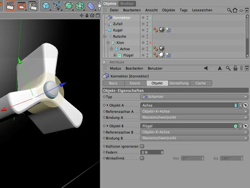
Once we have taken care of the actual function of the connector, we create it as a sub-object of the axis of the rotary wheel. As the axis is functionally connected to the impeller via the connector, the connector is in good hands here.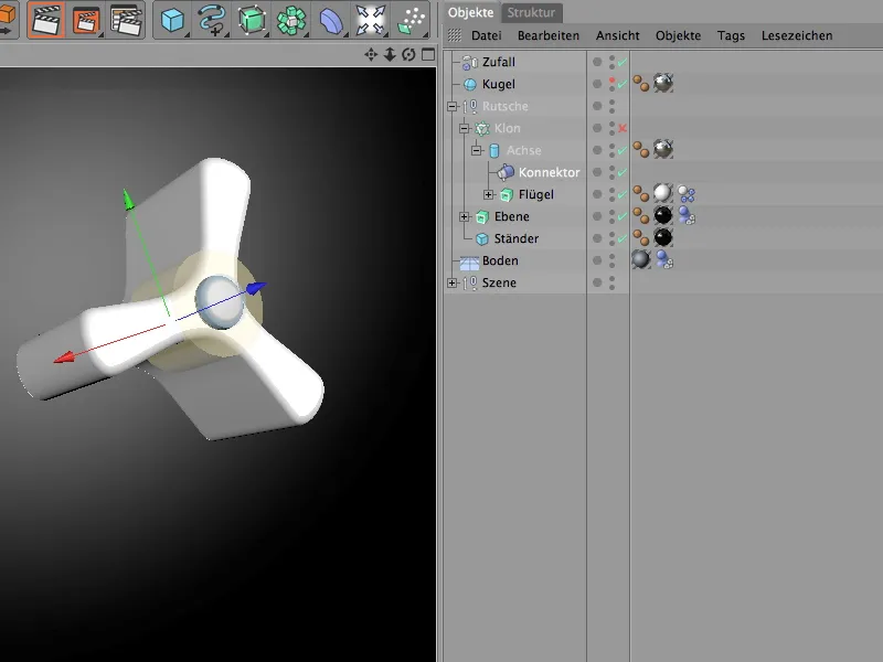
Generating dynamic balls with the particle system
The game machine is fully equipped and functional, now we just need balls with dynamic properties that we can release onto it. We already have a ball in the scene. However, to get the game machine working properly, we need to release more balls from a particle emitter. But first we give the sphere the desired dynamic properties so that it can participate in the simulation at all.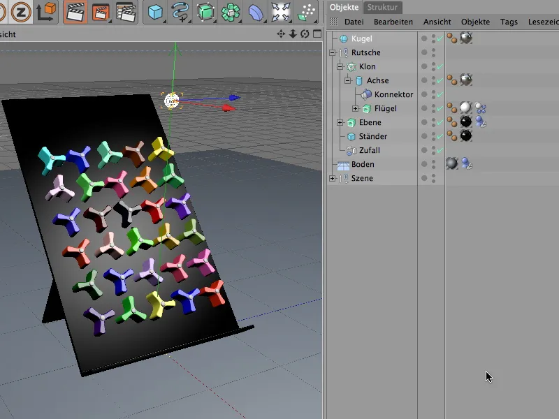
To do this, the sphere needs a Dynamics Body Tag with activated dynamic properties. So we assign this tag to the sphere object using the Create Rigid Body command from the Simulation>Dynamics menu.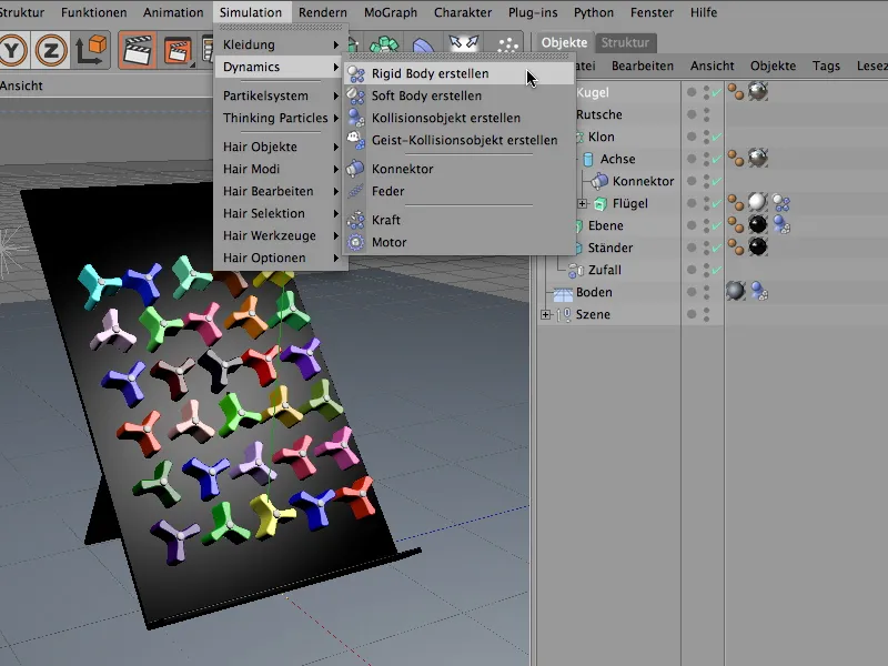
In the settings dialog of the Dynamics Body Tag, we find the basic properties on the Dynamics page. Here we set the resolution to Immediate so that the balls can take action as soon as they appear in the scene.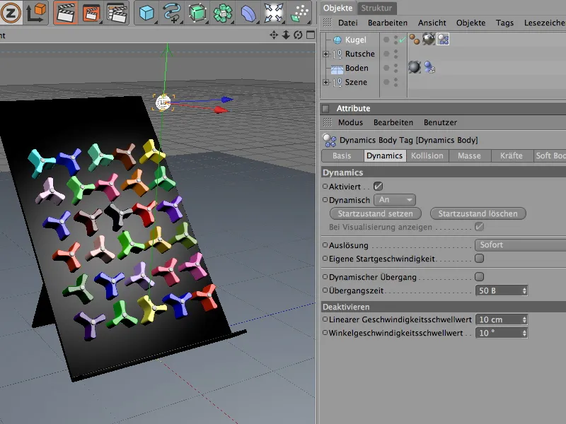
Let's turn to the collision properties on the collision page. A ball is absolutely unproblematic in the collision calculation; the automatic detection works here. The elasticity and friction of the sphere remain within reasonable limits. If balls collide with each other later, they will also bounce less far.
The settings on the mass side are interesting in connection with the settings of the rotary wheel. There we had our own mass of 8. We set the mass of the ball to a value of around 5 so that the balls do not hit the rotating wheels too hard and heavily due to too high a mass and upset the system.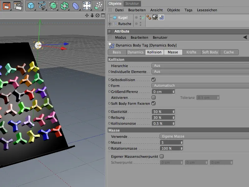
To ensure that the balls also come to rest relatively quickly after the rotation (analogous to the rotating wheels), we assign a damping on the force side. A value of 20% is sufficient for linear damping and rotational damping so that the balls do not roll out too far.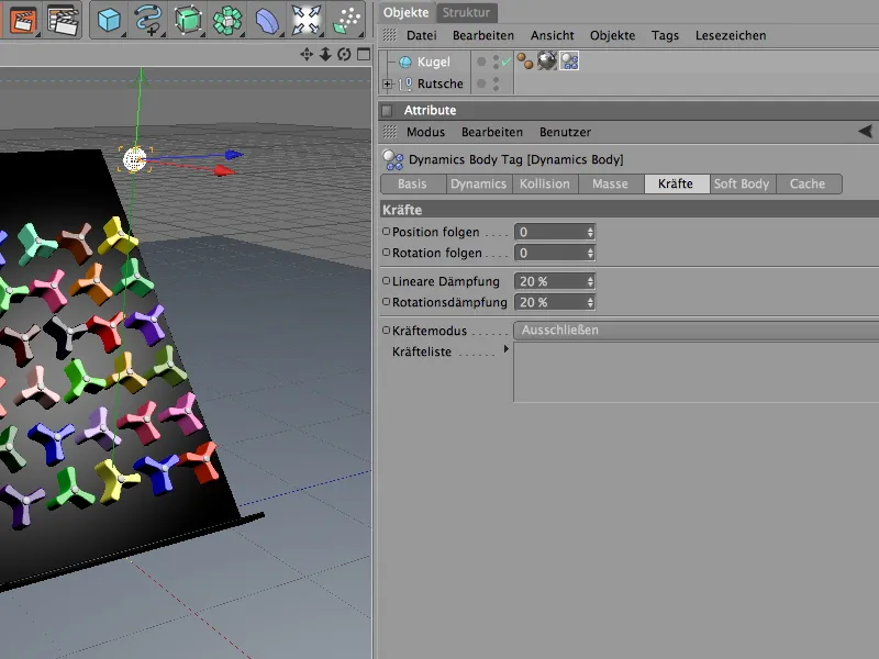
The ball now has its dynamic properties, but it is still on its own. To produce more spheres of its kind, we use it as a particle in a particle system. To do this, we need an emitter object that generates the sphere particles and sends them off. We can find it in the particle system objects palette.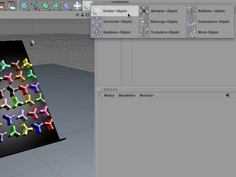
In the settings dialog of the particle emitter, we can define exactly how many balls are produced in which time and from which position. In order not to overtax the game device, I have opted for a birth rate of two particles (per second). The emission of the spheres is started immediately and ends after eight seconds, i.e. at frame 200. A sufficiently long particle lifetime is important so that the spheres do not disappear prematurely from the screen.
On the emitter page of the settings dialog, we define the shape and size of the emitter. Because the emitted spheres should utilize almost the entire width of the gaming device, we use an X length of 145 cm. The narrow 10 cm in the Y direction guarantees that the balls are emitted almost horizontally and do not fall from too high up.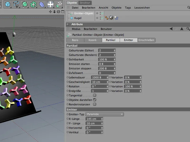
We now position the finished particle emitter on the upper edge of the game device using the editor view or the coordinate manager. When aligning, always make sure that the particles are emitted in the direction of the Z-axis.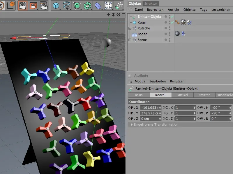
To assign the sphere to the particle emitter as a particle, we simply assign it to it via the Object Manager. The actual sphere object has now disappeared from the editor view and only appears in the form of the emitted particles.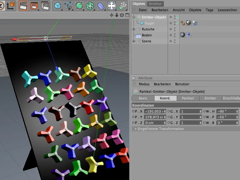
Global Dynamics settings
By default, CINEMA 4D has a gravitational force similar to the earth's gravity. These and more settings can be found in the document preferences on the Dynamics page.
On the Expert page, some default values can also be changed in order to better adapt the collision detection to the elements involved in the simulation. In our case, it makes sense to reduce the scaling to 10 cm and keep the collision tolerance as low as possible.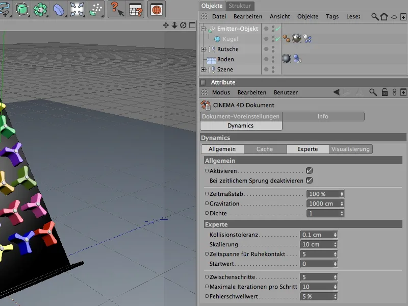
All the preparations and settings have now been made so that we can start the dynamics simulation by clicking on the play button.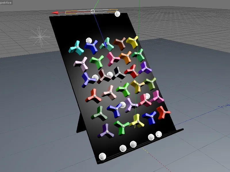
With this finished example, the effects of the dynamics properties can be studied very well. With different mass, friction or damping values in the individual Dynamics body tags, the elements very quickly take on completely different properties.
Have fun experimenting!